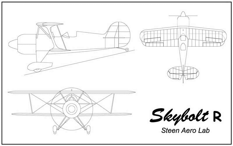
Mantua, New Jersey
Original Site:
September 2004
E-mail: usav8or@yahoo.com
March 2, 2014 Pain in the asses...
You just can't get around them...
when there isn't enough room.
Sunday... Sunday... Sunday... if I put enough time on the project today I just may get the horizontal stabs attached to the fuselage.
Had some time in the morning to work on the biplane... so I aligned the first bushing for the horz stab attach; the one that gets welded onto the fuselage. Had just a little bit more time so I figured out where the vertical tubes get drilled and welded into the stabs for the flying wire attach points. Marked the dims and then found top-dead-center and mark the tube. okay... out of time right now
Turned the light back on in the early afternoon. I'll get as far as I can go and then I'll be stopping. Ain't rushing anything... just makes sloppy work when you do.
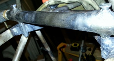
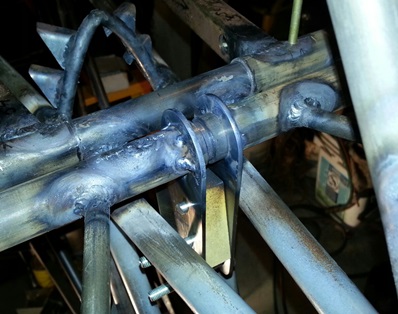
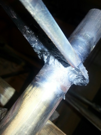
The first vertical bushing was already aligned and in place for welding. It was just a matter of becoming a contortionist... twisting and turning myself to fit inside the small, back-end of the fuselage. Top, bottom and sides needed welding. Wasn't as bad as I thought it would be except for the radius on the inside of the top and bottom welds. It was a tight space between the bushing and the rear turtledeck former.
I ran into a pain in the ass after that... match reaming out of the lower bushing to the top bushing. I didn't think I'd have a problem with it... Just wasn't a lot of room for turning the handle of the reamer. It was taking for....ever. Ended up... finally... using an electric drill. Worked like a champ.
It took quite a bit of time to weld in and ream out the first bushing. Wasn't quite sure if I'd be... ahhhh what the hell, I had time to do it... time to do it right. I repeated the same gyrations that I did with the first one. Must have learned some small technique because I had no trouble welding those inside radii. Used the same drill for reaming out this one too.
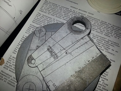
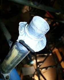
Front bushings welded in. These aren't the bolts I'm
using to lock it onto the fuselage.
March 3, 2014 The three steps of drilling these holes...
centering, standard and uni...
I'm finally able to move ahead with something new... The front attach for the horizontal stabs is complete and I'm moving on with it.
I'm so familiar with these stabs I might as well finish what I need to finish on them. I review the plans again to make sure that the marks I put on them the other day for the flying wire bushings are in the right location. Check. And I confirm the diameter of the holes I need to make; 3/8inch. Check.
I take the starboard stab off the fuselage and bring it into my kitchen (which has more room than the work shop) for a large, well lit, flat surface. A go through the usual centering bit, larger centering bit, drill block with smaller drill bit drilled through both wall... When I go to use the larger 3/8inch bit it just ain't centering on the hole and I'm not going to Jerry-rig it to try and get it close. Without hesitation I fetch the unibit and open up the holes to 3/8 on the one side. FLIP. Open the holes up to 3/8 on the other side.
Pull the port horizontal stab off the fuselage and repeat. An hour and a half and I'm ready to weld the bushings into the stabs.
March 8, 2014 Getting there...
finishing the horz stabs that is...
Plans for today... weld on the one and a quarter inch 3/8inch tubes onto the horizontal stabs.
I have all four cut, or, at least I thought I did. I count four, but for some odd reason... one of them has been reamed out larger than 1/4inch. No problem. I'll just cut another lenght, chuck it in the micro-lathe and square it up to size. Took close to an hour, but it's done. And with the micro-lathe back up and running I'm not relying on someone to do it for me.
I start the process of taping the bushings into place on the horizontal stabs and welding them in; starboard stab top side first, flip, then bottom side... then port stab top side first, flip, then bottom side. Today it was a challenge to weld the bushings because of the size of the stabs. At times I had to scooch up between the metal ribs in order to get a good angle for welding. Add another 1.5hours to the build with just this welding. Total for the day 2.4hours.
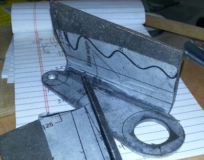
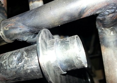
New bushing.
March 10, 2014 Back in...
to get something done.
Went out to the garage to put the elevators back on the fuselage so that I could align and weld on the elevator horns... Wait... that was kind of stupid; putting the elevators back on the fuselage before I place the horns on the elevator spars. And what about that spacer I had made for it ??? Haven't even done anything with that yet.
Okay... putting the elevators on the fuselage wasn't a total waste of time. I at least reamed out those freshly welded up bushings; reamed them out to 1/4inch. Other than that... yeah, just going through the motions of doing something.
Back inside and I take another look at the plans. See how the elevator horns need to go and grab a few things before heading down to the basement work shop; a few 1/4inch bolts, both elevator horns and the spacer. Needed to match drill the 1/4inch holes in the spacer with the two elevator horns. Not a problem... just need to go through a few steps to get it completed:
1. Clamp the spacer to one of the elevator horns.
2. Insert 1/4inch drill bit into spacer and drill hole.
3. Place 1/4inch bolt in first hole/spacer.
4. Clamp and drill second 1/4inch hole.
5. Bolt the two elevator horns together.
a. Use 7/8inch tube and 1/4inch bolt
b. Insert 1/4inch bolt into one of the spacer holes.
6. Match drill 1/4inch hole through other 1/4inch spacer hole.
7. Place bolt into first 1/4inch spacer hole.
8. Match dril second 1/4inch hole.
9. Done !!!
March 11, 2014 No... way.
WAY !
All this time I've been hoping this wouldn't happen...
Went out to the garage to align the elevator horns onto the front spars of the elevators. Dismantle what I had put together yesterday. Put the one on.
What ? Looks right but the ear of the horn is hitting the rear spar of the horizontal stabilizer. Went in and looked at the plans. Yup... I have it on right. Checked and cross checked all the dimensions. They're right too... but something isn't right.
Go back out and tried it again... you know... as if it's going to fit right this time. Same... damn... thing happened. The damn ears of the elevator horns hit that spar. What the heck is up with that ? The only thing I can think of is to cut the edges of the ears off so that they'll miss the spar. But that ain't right either.
Checked the mistakes and corrections page that is sent out with the plans... nuthin'.
Not sure how I figured it out but I did. It appears that the bend on the ears should be 1/8inch not the 1/4inch that I have them at. I confirmed this by taking a look at what Ward had posted to my post on the Biplane Forum.
As I had mentioned early in this post... I was hoping this wouldn't happen... and it did. You CAN'T make a bend on thick 4130 sheet metal and have it run straight unless you leave an excess of the material to bend over and then trim to size. I guess it's a kind of leverage ??? Well, I had less than 1/2inch of material to bend a nice, straight 1/8inch curve. My hammering over of the one only confirmed my theory. All the hammering only made a slight ripple along the ear. No tighter radius noticed at all.
All the work that I've put into these two elevator horns and at the last minute I see something that I should have done but didn't know to do. I was thinking I was doing the metal a service by not putting as tight of a bend on it. The only service I did was a disservice to myself.
Back to making a few more of these horns. I know what I need to do so it will go a lot faster. But it's just adding hours to the build... a part of that learning.
March 12, 2014 whatever...
WAY !
Home a little early tonight...
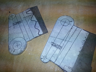
I'm glad I had a few extra drawings of the elevators printed out when I did 'cause I need them now. Cut the first set of elevator horns out of the large sheet of paper I had them and various other drawings printed out on years ago. Went down to the basement work shop found some .100 4130 and glued them on.
The throat on the metal bandsaw ain't that deep. I needed to flip the piece of metal over a few times to get the full cutouts... which resulted in the prints I glued on getting destroyed. Ahhh... that's why I had a few extra drawings of the elevators printed out when I did... (sounds like I'm repeating myself)
Back upstairs to cut another set of those prints out. Glue those on and cut them out to a close-to-rough shape. Took them to the grinding wheel and had my way with them. They're close to the line. Tomorrow... more work on them.
March 13, 2014 what comes natural..
will have to wait until tomorrow
Home a little early tonight...
I'm all too familiar with what I was about to do... filing and sanding the sides of 4130 to a smooth finish and then doing whatever comes natural.
Tonight it was filing the side of the rough cut elevator horns. Just a matter of time with these puppies.
Got both to the filed point and decided that I'd cut the holes in them before I finish sand to 400 grit and bend them.
My work so far... both filed and both holes cut in the one.
March 14, 2014 what comes natural...
on second thought... isn't so natural
Continued work on the new elevator horns.
Set the second horn up on the drill press... used a starting bit to get the hole aligned then followed up with a quarter bit. But before getting all the way through with the quarter I put a 3/8inch bit in there figuring why use the unibit all that time ??? (Going staight from the 1/4inch to the unibit.)
Well, I should have. I'm drilling away and when I pull the bit out I see that it has shifted to the one side QUITE a bit. No, not just a little... but close to the outside of where the 3/4inch mark was. DAMN !!! Not a problem... just a pain in the ass. I chucked a 3/4inch holesaw bit in the drill press and proceeded to put the hole where it was suppose to be THEN used the unibit to cut out the remaining metal up to the 7/8inch hole I needed.
The hole was still a little off compared to the first horn (off... but just a smidgin off) I drilled so I aligned them, locked them in a vice and evened things up to make them look purty.
Took the ol' dead-blow hammer to them and beat the hell out of them (after placing them in a vice with the 1/8inch bending block). Turned out just as nice as the first ones... just a tighter radius.
The ears still need to be cut down. And the outside edges need to be sanded down to that silky smooth finish. THEN I still need to drill for the spacer block I have for them.
March 15, 2014 A few too many...
hits.
Took a look at what I did yesterday on the two new elevator horns and wasn't too happy with it.
What I had done, just before calling it a day, was to re-clamp the one horn to hit it a few more times to see if I could bend the ear over more (to see if I could get it closer to the 1/8th inch radius). I didn't think that I did.
Today I cut the ears off to length, ground down to size and filed them smooth. I then compared the two and the one is bent a little different than the other one. Apparently I did some additional "damage" to it. It's good enough... but good enough isn't good enough. Thus I started making two more today.
Nothing new to write home about. It's a repeat of what I've done at least four times with these horns. The only difference today was that the 13/16inch cutter on the Unibit decided it was going to give up the ghost. The first time I worked through that level, on the first 7/8inch hole today, was a chore. The second time... it just wasn't happening. I basically had to hand file my way through that size opening so that I could cut the remaining 7/8inch size hole.
3.8hours of time put in... maybe 3hours of work was actually accomplished. All I can say is that they're ready for bending.
March 16, 2014 Sometimes we don't realize
we've already reached Excellence...
until a few tries later.
If at first you don't... ahhh, you know the routine, right ?
I need to bend the ears on these things now...
To get the tight bend RIGHT on the line I figured that I needed to back the sight line to the point where the bend will begin at the ear; it's foot. That site line ended up being about .125inches inside of the horn itself. Set the first horn up in the vice and banged away. Nice bend on it... Viced up the second one... banging away... comparing it the entire time to the first one for an equal bend... and got the second bend the same as the first. NICE !!!
Held both flat parts together to admire my work and DAMN !!! the horns are slightly twisted. Clamped them in the vice to get the closer to straight and they are closer... not straight though. Trimmed them down to the marked line then Jerry-rigged them up to the elevator in the biplane to see where they'd fall... and they fall STILL hitting the rear spar of the horizontal stab. DAMN !
Well... they weren't failures, but I thought that I could do a better job of it than the one I had; the one I was happy with. Spent the entire weekend making two more sets. AND the final set I made and bent today... not as nice as the ones I had that were hitting the rear spar of the horizontal stabs. AND, as I said before, they still freakin' hit the rear spar of the horizontal stab. (note: these horns arn't squared up... for twisted reference only)
So here is what I'm going to do. I'm using the original ones (actually the second ones I ever made) and reversing them on the elevator spar. I'm pretty sure that the bend for the extra strength can go either way. And... the aluminum spacer block that I had crafted to fit between the two horns is adding a lot more rigidity than the orignals anyway. The ones I just tried making are twisted. The twist won't allow the spacer block to sit flat on both horns. I know if I use it it will be more trouble than it's worth.
Back to Plan "A"
March 17, 2014 Working on Excellence...
The elevator horns of "Excellence" need a little work to allow them to swing each way...
25degrees in each direction is a lot of movement... for elevator horns which are so close to the horizontal stab rear spar and the tail-end of the biplane.
I'm putting them on per the plans way which means I'm cutting back the top part of the ears on each horn. As mentioned yesterday, the aluminum spacer block will be adding a lot of stiffness and the elevator horns on the Pitts... well, there's only one horn connected to two bearings.
To get a looksee on the travel I made up a quick paper jig showing the movement of 25degrees each way and taped it into place. A lot of back-and-forth but I finally got it to swing forward 25+ degrees without coming close to the horizontal stab's rear spar.
Here they are...
Still need a little bit more cleaning up.
March 18, 2014 A fix..
could create a mess...
Not sure why, but I was a little hesitant to go out to the garage work area to start the process of actually attaching the elevator horns onto the fuselage.
First thing was to put the horns on and then attach the starboard elevator.
As it turned out, leveling of the fuselage was the pain in the arse part of the entire deal. This took on the bulk of tonight's time. Once I got that leveled... I leveled the stabs front to back. Yesterday I had made a wood spacer block to insert between the horns while I fitted and tacked them in place (I didn't want the aluminum spacer block to melt).
Inserted the spacer with the 1/4inch bolts... not a problem until I swung the horns front to back in the 25degree arch... The don't hit the upper longerons, but the bolts stick out pretty far. If I had bent ears on the back (like some are doing) it would be even more of a problem... and I have the longerons spread apart slightly, per the "gotchas" in the Skybolt Manual to give it a little bit more room back there. Just a heads up, that's all.
To give a little bit more room for the forward movement I aligned the elevator horns a few degrees back past vertical. There's plenty of room for them to swing 25degrees forward and 25 degrees back without even coming close to tapping anything.
March 19, 2014 Even an extra 1/2inch for that added safety...
could create a mess.
Welding up of the elevator horns today ? I hope so...
Needed to take the elevator/stabs off the fuselage in order to weld these up. The issue I had was not being able to separate the spar of the elevators far enough before they hit the longerons. What I had thought was a good thing (making the tube that inserts from one elevator spar into the other longer than 1/2inch) was a very bad thing. After struggling with it for a long while I decided that there was only one thing I could do before breaking the tacks on the horns, taking them apart and cutting the sleeved tube to 1/2inch... and that was to cut the elevators from the horizontal stabs (which I didn't want to do).
No cutting wheels in stock here at the house for the Dremel so I had to resort to using the handheld grinder. It wasn't too bad, just a little overkill for what I wanted. Lucky for me the gaps between the stabs and elevators were large enough for me to use the grinder. (it's a crapshoot whether I add hours like this to the project or not... guess it depends on if I've learned something from it or not... instead of just time searching for a tool or part... I learned something today)
My FYI to you... keep that sleeved tube to a length of 1/2inch... sticking out past the end of the tube it's sleeved in.
The welding wasn't a problem at all. Went pretty smooth. Next... I'll be putting these puppies back on the fuselage and begin working on the turtledeck again !!!
Horn welded on starboard elevator.
March 20, 2014 It doesn't get much better than this...
Not so much.
Cut the sleeved tube down to 1/2inch. Made it a lot easier to put together than when I tried taking it apart.
Aligned the elevator horns and they lined right up. Bolts slid right in... Looked at the elevators to make sure that they were even with the horizontal stabs... and WTF ??? Seriously ??? One is about 15degrees different than the other ??? Seriously ??? They were perfectly squared when I tacked them ! I can bolt them together without a problem and they're THAT far off ???
Seriously ???
I'm not even going to try and figure this out tonight. I'll come back to it tomorrow. Maybe they'll miraculously line up for me. Dreams do come true... right ?
March 21, 2014 Wasn't as painful as I thought it would have been.
Am I getting use to fixing my mitakes ? or ???
happy knowing that all is not lost...
'cause I've been down this road before attitude ?
Bit the bullet and moved forward (instead of pondering what I will ultimately be doing... why wait ?)
The surgery on the elevators is going along better than expected. I cleaned the last set of horns that I made. Looks like the area that has a slight twist will be eaten up by the bead of the weld. I'll still need to see if they need to be notched like the first set.
That took a little over an hour... the cleaning up of the horns. Up the steps to the garage work area to strike the first blow... cutting off the first of the two eleveator horns (I hate doing this). It came off pretty easy. But... grinding down close to the spar tube wasn't much fun. I had to be slow and careful doing it so that I wouldn't ruin the entire elevator with an over zealous swipe of the handheld grinder.
After taking the horn as far as I dare with the grinder I started filing away the rest of the horn. Took a bit of time, but it was time well worth the slowness of the progress. Got it down even with the surrounding tube. Did a test fit of the horn and Wa-La, it fits !
One down. On left to go.
March 22, 2014 Going back in time...
again
A few more hours work on the elevator and elevator horns...
Needed to grind/file down the remaining horn on the starboard elevator. Took my time and did a nice job on it.
Took the elevator horns down to the drill press and drilled the holes for the spacer block. Clean/deburred them, then sanded them to a 220 grit.
Attached the port elevator onto the fuselage... test fitted the horn... Guess what ??? Even with the ear bent closer to the body of the horn. Even with the ear bent closer to the 90degrees. It STILL hits the rear spar of the horizontal stabilizer.
Tomorrow I plan on trimming the top of the ear on both and hopefully tack/weld these into place so that I can get back on the turtledeck.
Not clear here... but the ear on the new horn hits the spar.
March 23, 2014 One side...
at a time.
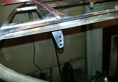
It took some doing (obviously), but now they're done... the elevator horns are welded to the elevator spar. They're in the correct location now... I'm sure of that. I welded up the starboard side then aligned it with the un-welded port... I made sure they lined up before I welded the port elevator horn.
Tomorrow I'll finish weld both sides of each horn (only did the one side today) and then get back on that turtledeck.
March 25, 2014 Horns are finished...
Back to the turtledeck.
nice...
Finished welding up the elevator horns onto the elevators. Basically welded the reverse side on each of the horns.
Cleaned both sides of the tubing up. Cleaned up the scaling on the inside of both tubes... then put them together on the fuselage and they're pretty tight without even using the aluminum spacer block. I'll have to find the wood spacer block so that I can lock these together to work on the rest of the biplane's linkage (don't want to be using the aluminum spacer block and getting it all messed up).
Here it is... looking good !!!
April 27, 2014 Spreading...
the load.
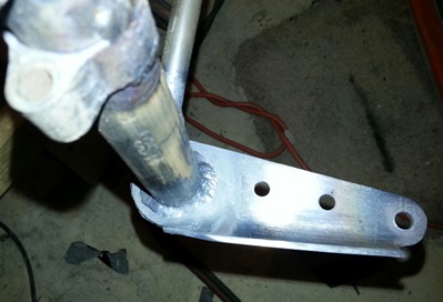
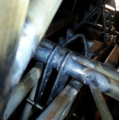
Just a little bit of work on the empennage today. Because of the cozine factor (you'll have to look that up if you haven't read it by now in my blog... mentioned a few times) the horizontal spar attachments are a little off of the vertical tubes. In order to make sure that the load is spread down into the two vertical tubes I've decided to make gussets to place below the attachment.
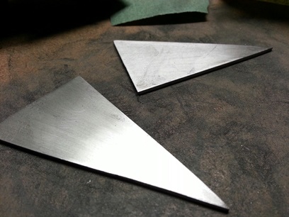
I've rough cut them out 'cause it was towards the end of today's session. Next time... I'll grind then file smooth... then weld onto the empenage.
Picture to come ???
Started to look at the tail wheel attachment again. Well... not look at the actual attachment, but looked at the plans to see how it is position on the tail post. Took the tail wheel out from it's storage to start fiddling with it. Need to do a little research on how/where/what to do about the springs for it...
May 1, 2014 Still Spreading.. it
A little bit more work on those gussets... Ground them to size and cleaned them up. They're ready for welding.
June 21, 2014 Do something on the project...
no matter how little it is.
Scratching my head looking at the Skybolt Builder's Manual. Kind of confusing... for a while. But then the light comes on and I'm understanding what they're saying.
The Builder's Manual is sorta like shuffling both the Skybolt plans and Mac McKensie's Firebolt plans together for this area. (As a side...One of the sizes on the plans is wrong.) In order to do it right you need to span the length between the port and starboard horizontal stabs. AND... since we're doing that we may as well go just a little bit further and do it the McKensie way; which is to sleeve a 3/8inch tube inside of the 5/8inch tube. aka... it's better alignment of both sides.
So, I wrap my head around that process and then figure out what I need and if I had any of that material. Dicovery: I have some, but not all the material; a few lengths of tube and a few bearings. Time to call Aircraft Spruce.
I always get itchy when I'm not doing actual work on the biplane. You need to read and understand the plans, right ? You need to figure out what materials you have, right ? Yeah... but that just ain't cutting it for me. Today, I discovered if I do just one thing on the biplane project I feel a lot better. It just needs to be one thing, and it doesn't even need to be that big of a thing. It's actually taking the statement my friend Howard said oh so many years ago... "Do something on the plane each day no matter how little of a task it is."
That something could be reading the plans or checking to see if you have the material for your next task. I'M saying take it one step further and do something on it. Touch the project !!!
I saw that the tubes/bracket that holds the reverser in needs to finish welded in. I "tackle" that project item and stand back to see what else needs to be done. Er, I stand back to see what I can do now. A LOT still needs to be done to it.
Looking at the plans... I need to finish the upper tank so that I can finish the upper wing center section. That's a matter of bending what I have at the house then riveting (I say as if it's not going to be a learning curve), cutting a few holes and having it welded together.
oh... I need to cut and fit the Joy Sticks. THAT's something that I can check off the list today. Searched around and found a 1inch x .o49 piece of tubing and cut two 14inch lengths from it. Taped the torque tube in position and slid the tubes into place. Made airplane noises the rest of the day.
June 22, 2014 Do something on the project...
without doing something on the project.
Because of the set-up of Beej's frame (he had purchased it) the tail wires from Steen didn't fit quite right (he'll be cleaning up and using the ones that came with it) It was my good fortune that he offered them up to me... and I of course snatched them up.
A new set of tail wires will be on their way... sometime this week. yeah man...
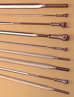
To the left are images of different flying wires that Steen Aero offers. The smaller of the wires are (I think) the tail wires. I will of course take a photo of these puppies when I get them some time next week.
June 29, 2014 Bending...
drill bits ???
Heading over to Woodstream Court today I'm thinking that I'll make the additional pieces for the trim servo area then move on to finishing up drilling the holes in the stringer stand-offs.
well... That's as far as the thought of doing something more than the additional pieces went.
I remembered to bring the CAD printouts of the additional pieces I was going to cut from some .o71 4130. Got to the house. Cut them out. Glued them on. Clamped the piece of metal to the drill press then began to drill the holes out. Using a centering bit I started the first hole then changed over to the drill bit I was going to use. Applied the pressure until the bit poked through the other side then slid the piece out to check the hole.
Looking a little oblong ??? Seriously ??? That must be part of the paper print giving it that distortion, so... I proceeded to drill the second hole. Clamped the piece of metal to the drill press then began to drill the holes out. Using a centering bit I started the first hole then changed over to the drill bit I was going to use. Applied the pressure until the bit poked through the other side then slid the piece out to check the hole.
DAMN !!! if the second one looked just as oblong !!! What the heck is going on here ??? Decided... that it STILL must be the paper pattern giving it that distorted look and proceeded to drill out the third and final hole. Clamped the piece of metal to the drill press then began to drill the holes out. Using a centering bit I started the first hole then changed over to the drill bit I was going to use. Applied the pressure until the bit poked through the other side then slid the piece out to check the hole.
CRAP !!! the third hole made it three ! What the heck ?!?! The bits are new. It's chucked in the drill press straight. I double checked the deck of the drill press and it's damn-near-close to being dead-on square. So... what is up with that ???
Drilled the three holes for the second piece that I had to make and ALL THREE WERE OBLONG just like the first three ??? (still) Seriously ???
Lucky for me I printed out a few additional patterns (yeah, there are moments where I do learn AND remember). Cut them out and glued them on the sheet of 4130. Let's try doing this again. So... Clamped a throw-away piece of metal to the drill press then began to drill the holes out. Using a centering bit I started the hole then changed over to the drill bit I was going to use. Applied a little less pressure (slow enough where the metal started to spiral up like a spring) until the bit poked through the other side then slid the piece out to check the hole.
DAMN... a perfect circle. Clamped in the piece of 4130 with the pattern on it and drilled the first hole... the second ... third ... fourth ... fifth ... and sixth hole. ALL were nice round circles.
Not sure what made me think to apply less pressure. actually... I think it might have been when I read the back of the bandsaw blade package (I just put a new blade on the metal bandsaw and on the package it stated that you shouldn't apply much pressure when feeding the metal into the blade, just let it go at its pace)... a little subliminal message that rose up out of the diluvial sludge, we call brains, at just the right moment (we'll not quite the right moment or I wouldn't have wasted metal and time) to help see me through with the completion of this task.
With the holes drilled I moved on to the next task (no, not finishing up the drilling of the stringer stand-offs)... cutting out, filing and sanding smooth, both of the fittings I just drilled six perfectly round holes in.
After thinking about this experience for a little bit (get it??? bit) I think that applying too much pressure can actually bend the bit to the point where it drills that oblong hole. At least that's what I'm thinking... today.
July 1, 2014 It's funny how...
you always end of doing things right !!!
Over to Woodstream Ct after work today. Started to do one of those "stand there and look at the part" moments... ones that generally take up a day or two for no reason at all. Quickly snapped myself out of it and got to the work at hand...
I've had most of these pieces for trim/servo tab since 2008. I'm surprised I haven't lost them yet. anyway... I wanted to get the guts of this trim/servo system made so I needed to get this task completed first.
Made my marks and grabbed the Dremel tool to slice the slots into the first, then the second, trim tab. Had enough of the metal cut away. Squared up the horn in the first one. Tacked it on. Finished the weld. Not happy with the look of it. Did the same to the second tab... not happy with the look of that one either. Remembered that I wanted to weld over the one mis-aligned hole on a stringer stand-off so I went over and welded it closed.
2.4hours had passed and it was time to head back to Philly. Still not happy with the look of the welds. Not today... but the next time I come back I'll grind those welds down and re-weld all those lines.
It's funny... one day I'm talking about taking the time to set things up so you do them right the first time and the next thing you know I'm welding the trim tabs standing there without either arm supported for a steady, accurate weld. There's something to be learned from this. Not sure what it is since I've been down this road before.
July 3, 2014 Going as planned...
by doing the unplanned.
Had the day off... a long 4th of July weekend/holiday. Headed over to Jersey about 10am... my 3rd class had expired and I had an appointment to get that out of the way (for another 2 years). Didn't take but a half hour. Headed over to the house on Woodstream Ct. to put a few hours on the build.
Wanted to re-weld the tab horns then move on to drilling the rest of the stringer stand-offs. Didn't take much time to grind down the welds (I'm not suggesting you do this on ANY part of your project... I figured these are non-structural pieces and after making a good weld I'll grind down slightly then file and sand to a smooth finish). This time I set them at the proper height. Supported both my arms and started stacking dimes. Wasn't hard... actually easier when properly done then when I was hacking my way through it the other night.
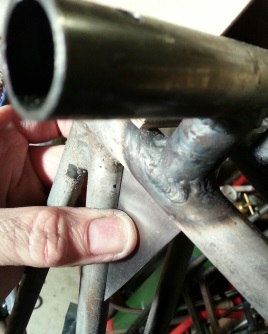
As I was re-welding those horns I saw a few places that still needed welding on the trim tabs. THEN... when I was welding those few places I decided that I'll just go ahead and weld over those open tubes on the horizontal stabs. Instead of making small washers and welding those on the 3/8inch tubes I just went ahead and welded over them using the 3/16inch weld rod. Made sure that there was plenty of weld rod in the weld then ground them down. Filed them. Sanded them smooth. The two larger openings I made 1 1/8inch washer and welded them in place.
These puppies are now ready for putting in the trim/tab connections (as soon as I order the parts, pieces and bearings).
Drilling of the rest of the stringer stand-offs ??? Maybe next time... At this stage of the project I'm finding that the growth/forward momentum sometimes takes on a life of its own; a natural progression of sorts. It's not just making bits and pieces anymore...
December 26, 2014
Making another list...
that I really didn't want to check twice...
As usual... had the day after Christmas off. NJDMV was open so I stopped by to re-new my month-expired drivers license.
With business taken care of it was time to have some fun... over to Woodstream Ct. to work on the biplane project.
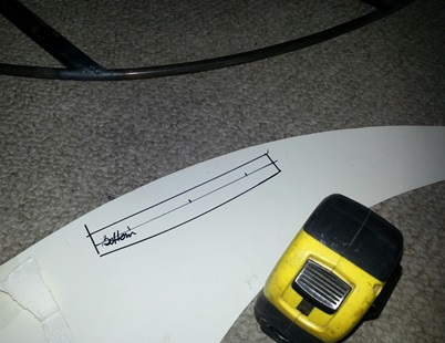
Just a lot of little things left to make and attach to the fuselage. Pick one... any one... and I'll make it. Pulled the mounting bracket for the rudder trim tab out of the air... Check the plans; it's 3/4inch x 6inches. Made out of .o32 4130. Took a piece of display board over to the rudder... drew the trailing edge to fit the curve of the rudder. Marked 3/4inch out from both ends and drew a straight line to connect the two. Measure and marked for three holes.
Found a piece of 4130 and traced the pattern. Marked the hole locations. Cut the metal. Ground down to size. Drilled the location holes. Filed and sanded the cut edges. Ready for welding on the rudder.
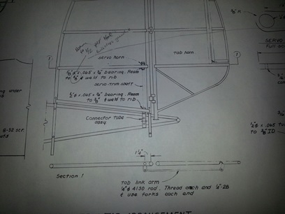
The next idea that landed on my lap was the trim/servo tab schtuff. I could have sworn that I took inventory to make sure I had everything I needed but... not so. Looked over the plans again to make a list of all the tubes that I needed to complete the trim/servo schtuff. As I looked them over I saw a notation that Hal said to change something from 3/8inch to 1/2inch. The note said it was mentioned in Hal's builder's notes. For the life of me I couldn't find those notes... and I know I have two sets of them. (I actually took 1 hour off the time I spent on the project today because I looked for these notes). I finally gave up the search and tried figuring it out. By looking at the various parts that need to be reamed and the parts that fit inside of said reamed part... I figured it out.
On the plans (page 14 of the Standard Skybolt plans) it says to ream the 5/8inch tube to 3/8inch. That's ain't so. There's a end tube, that is welded onto the 3/8inch tube that needs to spin inside of that 5/8inch tube. And... that tube is 1/2inch. So, ream it to 1/2 not 3/8inch. I need to order a few pieces of tube to make this trim/servo tab AND thinking it all the way through... I figured out I needed to purchase a 1/2inch reamer. I'll order these up this weekend. Maybe, hopefully I'll have these for next weekend.
oh... yeah... here's a few photos from the making of the mounting bracket for the rudder trim tab. Still needs to be welded on...
December 27, 2014 Two of everything...
the second time around.
Morning:
It's always funny (and I say always... 'cause it's happened more than once) when you do something... write it up... and it turns out to not be true. For instance: My lead-in statement on my July 1st post "you always end up doing things right." The statement will eventually be right BUT as of today it ain't. Looking over the trim/servo tab hook up... I'm studying the plans. I'm looking over the "Skybolt Manual" and something ain't lookin' right.
It turns out that the tab horn, the part that is welded to the trim tab, needs to be notched and welded to the leading edge of the trim tab not the back. I'll need to print out two more patterns. I'll need to cut two more blanks. I'll need to grind to size and drill the holes for two more. than... I'll need to notch and weld on two more. Eeeeeeeesh !!!
Day:
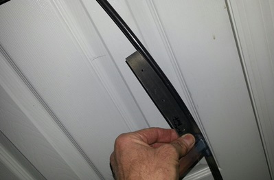
Headed over to Woodstream Ct... it's Saturday. Need to replace the trim around the garage door. So... first things first (the work).
Check to see if I had any extra lengths of 1inch thich lumber around ('cause I always do). And I did. A few 8inch wide pieces; an 8foot and a 6foot??? Something like that. Ripped them down to 3 1/4inch pieces. Primed then painted them. They're ready for hanging. (I did this over a period of a few hours in which I then shuffled in work on the project.)
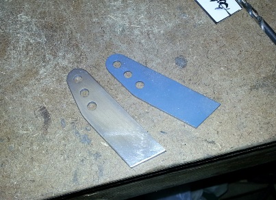
I thought I needed to print out the pattern for two tab horns with no means of printing them out until this week at work. So... I was thinking I was going to have to find something to do... one of those "stare at the fuselage for a few hours" sessions. With nothing to show for it. But, Lady Luck was with me today. I had a "spare" tab horn laying around that I could trace to make not two, but one tab horn (I gots the one already).
Did the usual glue-the-pattern-to-the-4130-cut-out-grind-to-size-file-sand-drill-holes... Aligning them on the trim tabs... another story. Hal writes in his "builder's maunal" to make sure that the holes on the horn fall below the hindge for the tab (this will eliminate differential tab movement.) To get the vertical line below the hindge I hung a weighted string over the center point. Made sure the elevators and stabs were level then held the horn in place and made a mark. More of a pain in the ass than it sounds. Did I say it was more of a pain in the ass than it sounds ???
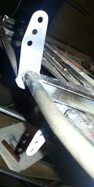
Tacked them both in place. They're ready for welding.
One new horn. One old horn.
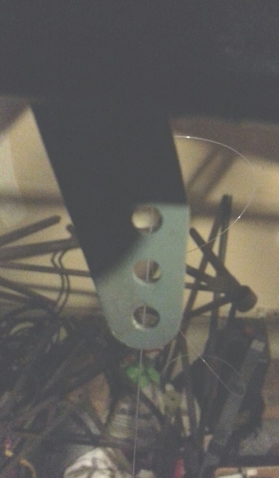
Line drop... keeping the holes under the hinge line.
One line of weld holding it on.
December 30, 2014 Two of everything ?
Now just one...
Ground off the first set of tab horns and welded them shut. Completed the welds on the new tab horns. Not much else to say about it. I'll need to get a photo of them and post it (as if I ever remember to do that after the fact...)
January 3, 2015 Nope... didn't remember.
Took the photo for another reason...
Here's a shot of one of the trim tabs back on the elevator... ready to be hooked up (once I start working on the trim/servo system of which I'll be ordering the tubing for this week).
January 8, 2015 Snow Day...
No work on the plane though...
Had to wait until a no snow day.
Yep... it's been a few days. Had snow on Tuesday... my day for coming over to Woodstream. (It wasn't a complete waste of time. I spoke to a fella about the engine mount.) but.. back to the trim/servo system. Was able to get over to Woodstream on THURSDAY !
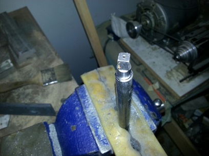
Ordered tubing the other day for the system and the engine mount. Checked the plans again to make sure I'm doing what I'm suppose to do and then began reaming and cutting. Didn't get a lot done in 1.3 hours but it wasn't a waste of time...
Reamed and cut the connector tube assembly. Reamed and rough cut the two servo horn "sleeves". Didn't have a 1/2inch reamer so I brought the 5/8inch x .o65 tube home and asked Andrea if she could ask someone at work if they could do it. And that, my friends, is all I got completed.
Need to ask the group what forks I need to be using on the tab link arm.
Update 1-9-15: The fork should probably be a rod end bearing. And that bearning would be a FAFNIR REPB3NFS464 for a 1/4-28 thread. It was suggested that I may want to go with a section of tube (either 5/16inch or 1/2inch). I decided I would go with 3/8inch with a threaded rod end (AN490HT6P) welded to both ends for the rod end bearings to connect to. Bearings = mo money ! Lots of mo money !


 Held both flat parts together to admire my work and DAMN !!! the horns are slightly twisted. Clamped them in the vice to get the closer to straight and they are closer... not straight though. Trimmed them down to the marked line then Jerry-rigged them up to the elevator in the biplane to see where they'd fall... and they fall STILL hitting the rear spar of the horizontal stab. DAMN !
 The surgery on the elevators is going along better than expected. I cleaned the last set of horns that I made. Looks like the area that has a slight twist will be eaten up by the bead of the weld. I'll still need to see if they need to be notched like the first set.
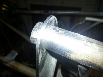
 Because of the set-up of Beej's frame (he had purchased it) the tail wires from Steen didn't fit quite right (he'll be cleaning up and using the ones that came with it) It was my good fortune that he offered them up to me... and I of course snatched them up.
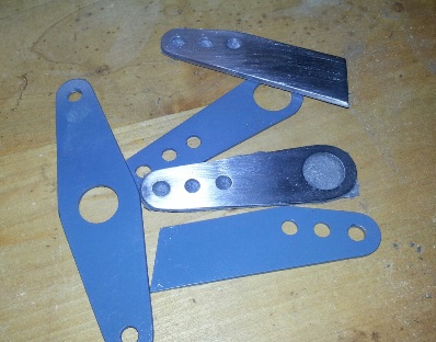
 Over to Woodstream Ct after work today. Started to do one of those "stand there and look at the part" moments... ones that generally take up a day or two for no reason at all. Quickly snapped myself out of it and got to the work at hand...
 As I was re-welding those horns I saw a few places that still needed welding on the trim tabs. THEN... when I was welding those few places I decided that I'll just go ahead and weld over those open tubes on the horizontal stabs. Instead of making small washers and welding those on the 3/8inch tubes I just went ahead and welded over them using the 3/16inch weld rod. Made sure that there was plenty of weld rod in the weld then ground them down. Filed them. Sanded them smooth. The two larger openings I made 1 1/8inch washer and welded them in place.