Mantua, New Jersey
Original Site:
September 2004
E-mail: usav8or@yahoo.com
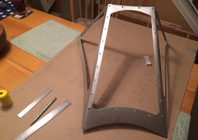
more work on the...Radial Fuselage.
January 1-6, 2017
I can see clearly now...
the windshield has windows !
Getting things accomplished with the windshield... "full steam ahead!".
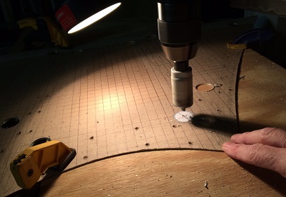
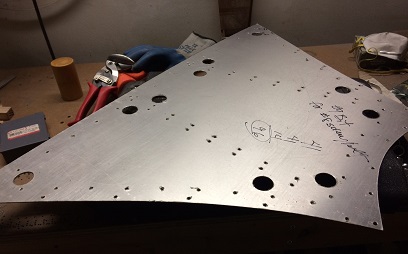
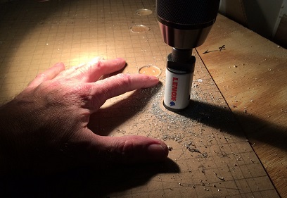
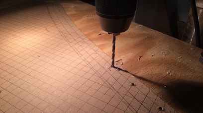
Drilled the corners holes for the windows the next night. Same as the 96 other ones but took much longer having to cut those 1 1/8inch holes with a hole saw cutter; centering bit, hole saw cutter, deburr.
Next I needed to notch the back-end of the blank; on the ends where it would meet up with the fuselage, and the two areas where I would bend the piece. Started off with drilling relief holes in the corners of those cuts so that I wouldn't have a 90degree cut where it would tend to crack over time. I then cut away all the excess... followed by bending the back edge over (basically to capture the back end of the plex so that I wouldn't be seeing the raw edge of the plexi.
Followed all this up with bending the two angles on the piece by putting it in my Work-Mate (does Black and Decker even make these anymore?)... putting an aluminum "L" angle behind it to make sure that I had a perfect straight edge to bend it against. Bent both angles. (note: I should have notech the center notches about 1/2inch wider as to avoid smashing them in the "vise" of the Work-Mate) Not a problem though, just needed to pry the smashed end up a little, but... if I have to do this again I would make the cut over the outside facet about 1/2inch wider. Okay, with the windshield bent, and the capture in the back re-opened I grabbed my cutters, both left and righ-handed ones. Proceeded to rough-cut the openings for the window.
I feel pretty monotonous with writing all this like I am... I then filed and sanded the openings to the lines makig sure there were no burrs or rough edges. Standing back... it looks good. I'm happy with the results of my work.
One thing... thinking back on it now, that I would change is instead of bolting the three attachments that will connect the windshield to the fuselage (that I still need to make) I would rivet them on. As of right now, I'm going to need to put anchor nut plates in place in order to bolt them on. Unless I just say, screw the holes you won't see them... and rivet the pieces on anyway? Naaaaaa....
January 8 - 13, 2017
WOW...
I'm back to WOW's !
Damn it ! I just can't let things be...
Back to making another one of these windshields. I guess if I was just trying to push through this project to have a biplane I'd say "screw it". But with the few additional things I learned from making the final one I'm saying "I can make a better one, and I'll do it now!".
Back to:
- Drawing the grid again.
- Deciding on what I want to change.
- Hours of drawing up the pattern by hand, again.
- Figuring out where I want the relief holes.
And... that's pretty much where I'm at after six days of additional work.
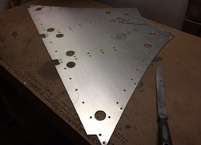
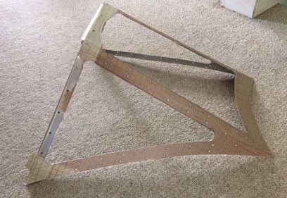
Just made windshield sitting on pattern of newer windshield.
A few things that I changed:
- Made the width of the posts wider.
was 5/8, now 3/4
- Placed attachment holes off the corners of the glass.
- The forward bracket holes were too close to the post bend.
adjusted the spacing of those holes
- Changed the cuts in the bends in the trail-edge.
"V" instead of squared off.
- Will make trailing-edge bend after bending to shape.
- May change the glass attachment screw size.
now #8 bolt, may change to #6
January 17 - 20, 2017
We're seeing some of that...
"90 percent finished and 90 percent to go" !
The entire project is made up of "Excellence"; doing the best that we can do, above and beyond the "aircraft standard" that we need to meet. But, we need to push ourselves beyond that "the best that we can do" and do things a little better when it is sitting out there for everyone to see...
Not a lot of work on the windshield this past week. More thinking... than doing.
I decided to attach the brackets, for attaching the windshield to the fuselage, with rivets instead of screws/bolts. Cleaner look, well and it will be easier for attaching. If using screws I would then need to use anchor nut bolts which means... blah blah blah. I should have decided to do it this way the first time (what was I thinking???).
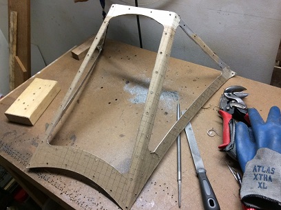
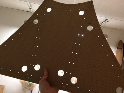
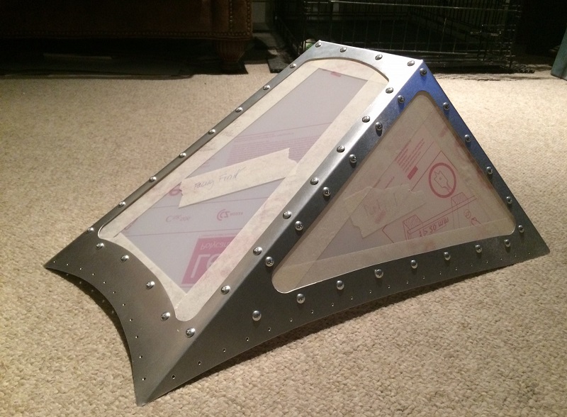
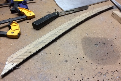
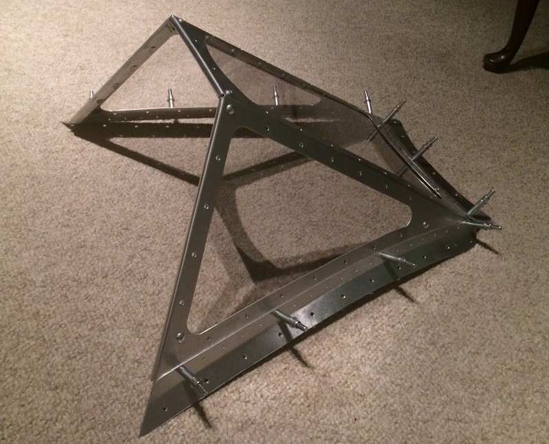
Here's where it stands so far. Still need to drill all the additional holes, then bend it to shape, then cut out the window openings then file to shape.
January 21 - 26, 2017
Still working on that...
"90 percent finished and 90 percent to go" !
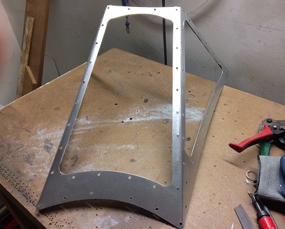
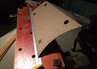
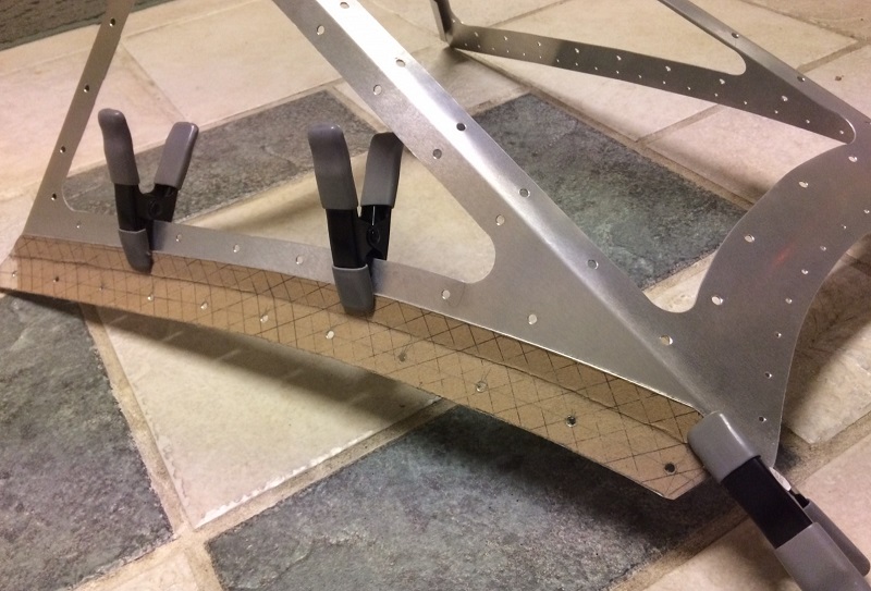
Continued work on the newest windshield. As of Friday, January 26th, I'm to the point where I have it bent into three facets and the window openings roughly cut out. It's all a repeat of what I just did... all blah blah blah now.
I'll need to file the openings to the lines then bend the trailing edge over and it will be ready for the glass. of which... I bought some 1/8inch lexan for making patterns for the final pieces.
January 27 - February 11, 2017
Still working on that...
"170 percent finished and 10 percent to go" !
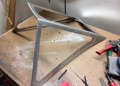
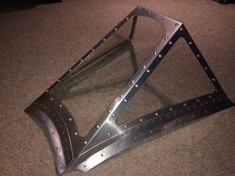
More work on the faceted windshield. It's there now... it's there...
Finished cleaning up the windshield frame; filing and sanding. Moved on from there to making the paper patterns for the glass pieces I'll be cutting and drilling. THEN cut the lexan test pieces...
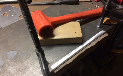
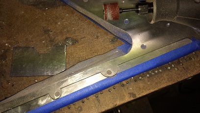
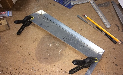
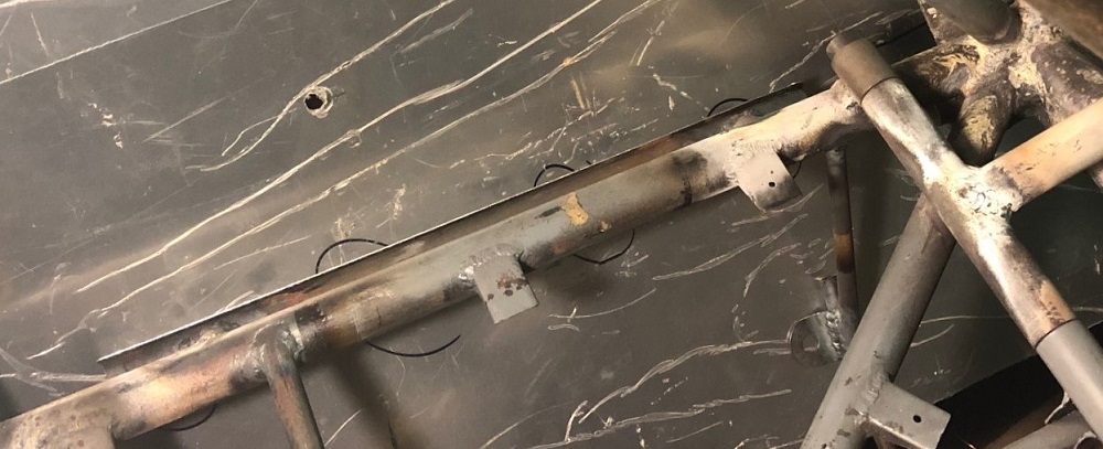
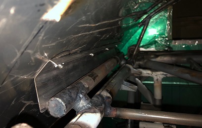
BUT, before I do any of that, I needed to notch the bottom of the trailing-edge wrap. The wrap comes around and covers up access to the bottom of the hole. Made up a few patterns and glued them in place... notches to allow the nut to spin on the machine screw. Free-hand it... was good enough... but good enough isn't good enough. Thought about it for a while then decided I'd notch a piece of 1/8inch 4130 with the large round file I have. Clamp that to the trailing-edge and put a drum-disc on the Dremel and have at it. Worked like a charm. Should have done that from the start.
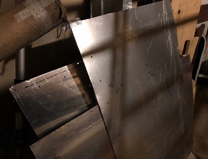
Note: angle of camera makes the original notch look WAY OFF... it was pretty much centered over the hole.
Notch on left - old, notch on right - new
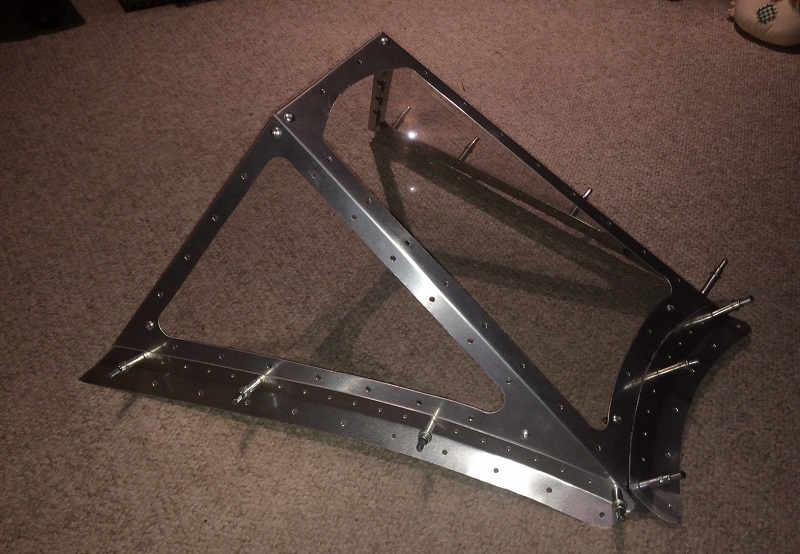
Received the number6 machine screws from Aircraft Spruce. Discovered that the nut I researched on line for thickness... is half as thick as what I was told. Add that to the few threads that I would leave show (for safety), they're about 1/8inch too long. WAY TOO LONG... when you're only talking about a 9/16inch screw. DAMN !They twernt that much money. I'll wait until I have an order for some additional items before placing an order for the shorter one... the cost in shipping would be the same as the cost for the screws. At least I had the screws so that I could now begin the process of drilling out the holes then attaching them to the frame to make sure all the holes lined up. Did this with all three pieces. Decided on a number 12 drill bit... Easy-peasy, other than the amount of time it took to do it.
Still work to be done. Need to figure out and make the attachment brackets. I'll need to figure out the bend in the fuselage and bend them somehow. After accomplishing that, I'll need to rivet them onto the above piece.
February 12 - 17, 2017
Now the brackets...
the last parts to be crafted !
Spent more time thinking this week... than actually doing. It's a good thing... 'cause if I just forged ahead with each thought I'd be wasting a whole lot more material.
Working on the bracket for the windshield to fuselage attachment... wanting to make the curve on the bracket with an english wheel, which is several hundred dollars. Hoping to find one on Craig's list... but nothing at the moment. Thought of finding out the bend, making a pattern of the bend, and then hammering it out. Still... was there an easier way of doing it?
Took another look at the pieces I needed to make... the bend was actually made by the radius I had on the windshield frame that I made... or so I'm thinking. All I need to do is bend the piece to that radius and ??? The more important question... how do I make that radius and have it look nice?
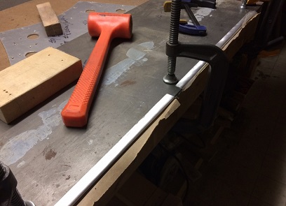
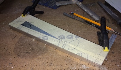
That beader I have won't work, the amount of material I could put in there before it beading isn't more than 3/8inch or so. Keep thinking... a few days go by with several thoughts, then I remember what Tony B showed for making flanges... Cut the depth of the flange in a piece of wood and work it slowly across the piece. I had some hard wood lying around so I cut a piece about 6inches long by 1inch wide. Cut the depth of the opening to 1inch... gave it a try. Worked pretty good... just need to keep an eye on making sure that the material is always inserted all the way to the bottom of the cut. Also... make sure that the excess material is cleaned off the edge after cutting the original piece... all that aluminum build-up makes it hard to insert it into the opening.
After figuring all the above out I tried a test piece or two... to make sure all my figuring out was thorough.
Need work on my technique.
MUCH better.
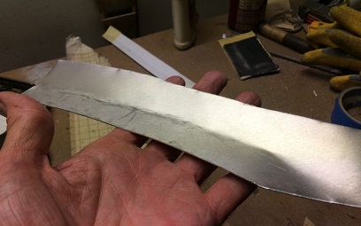
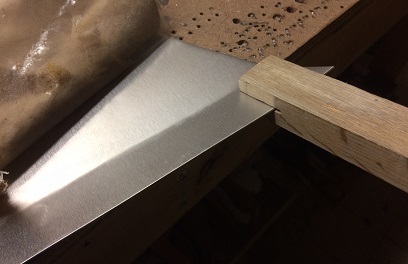
Everything checked out fine so I drew up the blank for the starboard side bracket... Used the pattern to set the curve for the piece and cut it out and cleaned it up. I then set the adjustable square to 1inch and used it as a guide to make the line for the bend. Laid the pattern back on the aluminum to draw the upper half that attaches to the windshield (I had that all figured out ahead of time). Used the adjustable square as a guide again to draw the 1/2inch mark and then spaced out the holes, marking every 2inches. Used the flanging tool to carefully make the end close to what I had figured it needed to be (had the actual windshield on the fuselage and used my adjustable angle finder to figure out the bend needed).
Took the piece back over to the bandsaw and cut the top edge to shape, then filed and sanded for a finish profile. Below are the results...
WOW ! Looking good...
February 18 - 23, 2017
Still on these brackets...
But, I'm almost there...
This all could have taken a lot less time that it has. More thinking about what to do... a LOT more thinking, than the actual work done.
Finished up the drilling of the rivet holes in the final side bracket and the front bracket. Spent another night match-drilling the rivest holes into the brackets.
I didn't have the correct length of rivets so I took about 70 longer-than-needed rivets and filed them down to the correct size. And that... my friends... is where it stands!
All I need to do is now rivet the brackets onto the windshield and she's ready to be attached to the fuselage.
February 24 - March 9, 2017
Pretty pathetic...
my current rate of posting...
Most of the time I've been currently spending on the build is either, a re-hash of me making the windshield for a second or third time... or me thinking through the instrument panel (my current work).
What's to write ??? "Jeez... can't find my layout I drew up for the instrument panel and I've been 1. searching for it, or 2. trying to figure out why I put those size holes and what's supposed to fill them." Thus... my silence.
Anyways... I finished up the windshield. Had a little backlash from one of the guys on the biplane forum not understanding why I wouldn't use an aircraft grade aluminum for the windshield (one that is harder to work with and serves no other purpose because it's not structural). Like I said on the post... if it's used on a Stearman's windshield it works for me. I'm MORE than happy with the way it turned out.
Wanted to continue on the sheet metal but didn't have enough left from the last time (which reminds me...). Looked at the instument panel and that's where I've been since. And you know where I am with that at this moment... figuring what I had decided on as far as instruments and toggle switches and breaker locations. Think I have it figured out and decided to make a side panel. I just may be wasting my time... but, I'm moving towards something. AND... it always seems when you're stuck... moving forward in any direction, whether the right one or not, will get you back on track.
Overhang of aluminum extrusion in photos below are not a part of the panel.
Back-side
March 30 - April 21, 2017
Still... pretty pathetic...
my current rate of posting...
Let's see... what excuses can I make for not posting ??? It's baseball season and I'm watching the Phillies (which isn't a lie). This electrical reading is boring and I just push it off (which is close to not being a lie). The 100 yard stare... where I'm standing at the project but just thinking things through... not getting much accomplished (which isn't a lie).
But... why no posts ? Just haven't had much new to write ? And you know what the really sad part about it is... me writing about my non-posts may be the most exiciting thing I'm writing about today!!!
Spent Saturday, April 21, working on the sheet metal again... about 2 hours worth of time and about 1/2hour of real work. Fitted up the panels that I drilled out a few days prior... (a little back-story: made a jig to hold the drill bit centered in the 2/8inch hole in the tab so that I could drill the holes while the skin is on the fusleage. Bad Idea! The bit still wanted to drift. Needed to mark the hole location THEN take them off the fuselage. THEN drill the holes mostly free-hand. Then...) They fit rather nicely. NOTE: I'll be over-size drilling the underneath panel slightly to allow easy alignment with the hole in the overlaying aluminum sheet. I can then match drill the side rail holes for a nice fit and finish. Yes ???
Spent about 1 1/2hours on getting the fuselage ready for turning it over; taking off the horizontal stabs, cleaning off all the stuff I laid on the project while working on it, and... fitting up the front rotisserie so that I can flipped the fuselage to figure out the side rails between Station 0.0 and 24.0. I tried just turning the fueselage on the saw horses (when I had the old side rails on) and it bent the rail from the weight of the fuselage. I've rigged up the front rotisserie and will just need to take away the front horse, go to the back and twist it 180degrees.
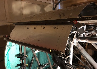
Skin patterns drilled and ready for testing.
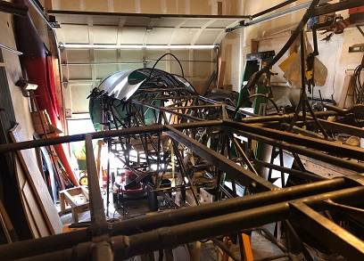
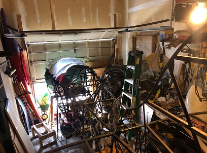
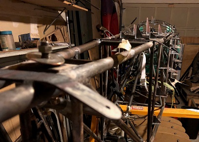
This shot gives you the feel of how the fuselage narrows from the HUGE engine/firewall.
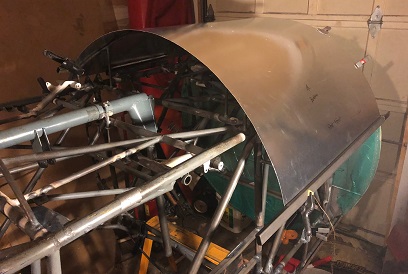
Good view of my "work shop". Nice shot of the big to little width of the fuselage.
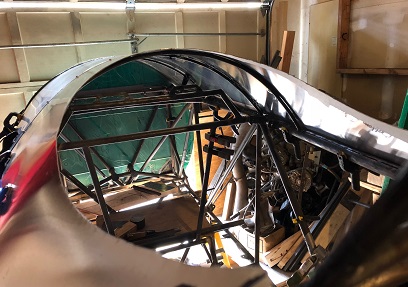
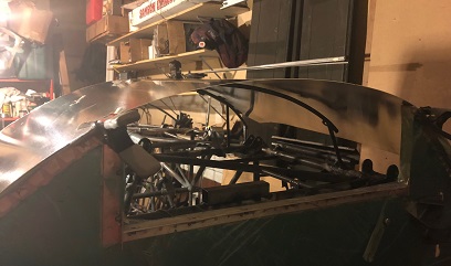
Shot of what it looks like in the cockpit. For what it's worth.
April 23 and 27, 2017
Ditto on...
my current rate of posting...
Wow. WOW! I'm going to keep saying WOW until I get back into building this biplane again. I'm saying my posting is pretty pathetic, when in truth it's my time on the biplane that takes the cake.
Eeeeeeeeeeeeeeeesh ! Get over the slump, Jerry!
I love it when I'm building it. I love thinking about building it. SO BUILD IT !!!
Spent a load of time setting up for the flip of the fuselage. Load of time... aka 1/2 hour ? But still, I should have had it done in less than five. But, now I have it set up and ready for the five minute flip (off my soap box).
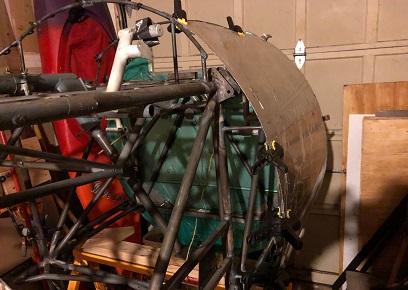
Monday I did the flip and clamped a piece of .032 aluminum on the port side to see how it looked and it looks DAMN FINE! This puppy is going to be a beast!
Flipped.
Testing sheet metal to lower, port side.
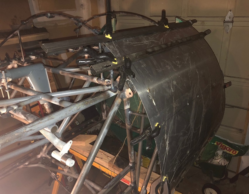
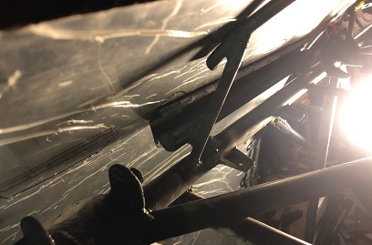
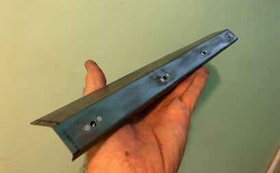
A bit of a hiatus from Monday to Friday??? Yeah? Back out to the project on Friday and started fitting up the port, lower side-rail (the piece that I made that has the anchor nut plates that I'll use for attaching the lower side skin to.)
A few clamping and un-clamping of the side skin. Center the rail over the stand-off I made and tape into place. Took the side skin off to mark and drill holes for attaching rail to skin. Fitted skin back into place and marked for trimming. Note on trimming: I need to cut down the width of the overlaying piece on the stand-off so that the edge of the rail hits the stand-off for welding. Make sense?)
Ready for trimming tomorrow and possible tack welding?
Outside view of side-rail fitting.
Inside view of side-rail fitting.
May 2, 2017
WOW...
an overstatement for current rate of posting...
Wow. WOW! I'm going to keep saying WOW until I get back into building this biplane again. I'm not there yet!
Wednesday... yeah, one day this week, attached the side-rail to the aluminum skin pattern. Needed to flip the fuselage back right-side so that I could get at the areas I needed to tack the side-rail on.
That's it! Nothing more... this week. Ugggggh!
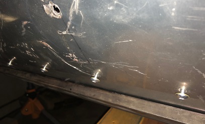
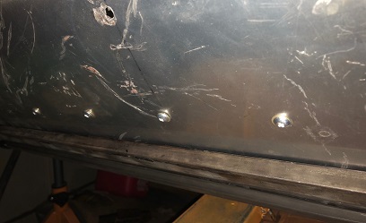
Indside view of area I worked on one day.
Bolts out and in position for screwing in.
Bolts in... ready to tack the side-rail on.
As you can see from my above photo posts... I ain't got much to write about. 'Nuf said.
May 6 - 21, 2017
WOW...
Still an overstatement for current rate of posting...
Wow. WOW! I'm going to keep saying WOW until I get back into building this biplane again. I'm not there yet!
I think I'm working on it a little bit more than in the past???
It's still a pathetic pattern... barely working on it. I did accomplish a few thing on the project. I did manage to re-do the lower, starboard side-rail. Not that I wanted to... and that my friend is where probably some extra time was added onto the project. I'm not talking about the time I spent on the new side-rail, I'm talking about the time I thought "Can I make the old side-rail work, or do I really need to make a new one?". I knew the second that the thought occured to me that I needed to re-make the side-rail, but I debated it nonetheless...
After I flushed out my final decision, I picked up the extra side-rail piece I had bent up with the final pieces I had bent a few months back with Tom. Gathered my riveting tools. Filed (remember, I wasn't happy with the cutter so I jig the rivets and file them to length... giving me the square ends I needed for riveting) the rivets to length... then started riveting.
After riveting the anchor-nut plates on (four of them), I marked and cut the piece to match the piece I was replacing. Back out to the garage to fit it up to mark the leg to size... back down to the basement work shop to cut, file and sand to size. Back up to the garage to bolt it back onto the belly-jig skin for a final fitting... and... now it's ready for the tack welds to hold in place.
There ya go... I spent a length of time writing about what I did without really saying anything worth reading...