Mantua, New Jersey
Original Site:
September 2004
E-mail: usav8or@yahoo.com
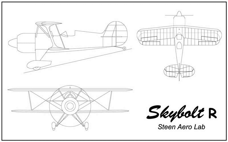
Building the Skybolt
aka Radial Engined Skybolt..
February 4, 2016 Sometimes hesitation is best served with...
figuring it out from a different angle.
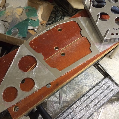
I'm feeling much better about the instrument panel tonight... Decided that I need to attach the flanges on the top of the back pit's face plate and move forward from there. All that hesitation with drilling and riveting the holes along the vertical edges... I guess, stems from the uncertainty of the spacing/look of the rivets along the top edge ? Not sure... but with me working on this top flange I'm feeling better.
Already had the holes drilled for the rivets to attach the arched piece to the face plate itself. Needed to figure out the spacing of the holes for the screws that will attach the top piece of aluminum to create the shell. But, before figuring out the spacing I needed to figure out what size screw to use, which would determine what size anchor nut plate I would use.
I used a 10-32 on the firewall... which is too big for the instrument panel. But... I don't want to get too small. I decided on 8-32's, and DAMN, I just placed an order from Aircraft Spruce the other day with delivery tomorrow, and it didn't have any of those in it ! DAMN ! I hope I have a few 8-32 anchor nut plates around (as if I would just have some lying in wait of me to use them ???).
Did a little looking around and DAMN ! if I didn't have a few packages of them. Nice !
Looked up the size hole I needed to drill for a loose fitting 8-32 and saw that it would be .177. Wanted it looser than that since I was drilling a clearance hole for the nut to pass through to attach with the anchor nut plate. Used the next larger size...
One inch spacing worked for the arched area so I marked for the holes, set up the drill guide on the drill press and started making the starting holes with the centering bit... followed by drilling the final sized holes. Finished with that task I then drilled the relief holes and rough cut the notches on the other leg of the "L" flange. Still need to file and sand smooth.
February 5, 2016 Needed more light...
and less holes...
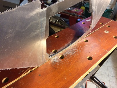
Filed and sanded the notches on the flange. This is the one that bends across the top of the curve on the back instrument panel.
I needed more light... as I started to match-drill the flange to the top of the face plate. I wanted line up the flange as close to the edge as I could without going past it. Hit the mark... most of the time. I guess I need still more light 'cause I was short the edge in the very center close to 1/32inch. Not a problem... I'll build that area up slighting with a thin washer or two to fit, if needed.
Also, the holes along the top, for riveting the flange on, are too far to the edge. I didn't take into account the vertical "U" stand-offs that I've been working on all this time. I went crazy on it; one too many on each side. I'll need to buy a little bondo to fill in those two 3/32inch holes.
February 6, 2016 "Screw it???"
HELL NO !
With the "oh shitters" from yesterday...
This morning I was thinking about what I needed to do with the mounting of these raised face plates on the instrument panels and almost said "screw it". I was that close to not even trying to do it. (I don't think that I would never try to do something... but I did think of it.) Throwing out that thought and getting back to the task at hand... I have a pretty long day ahead of me and I want to complete as much of this out as possible.
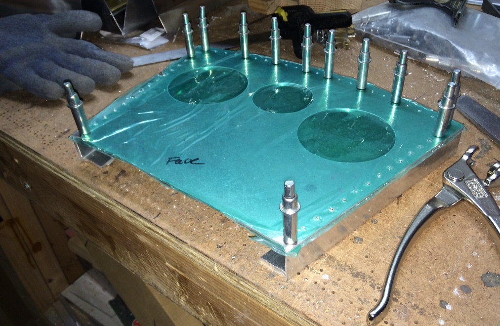
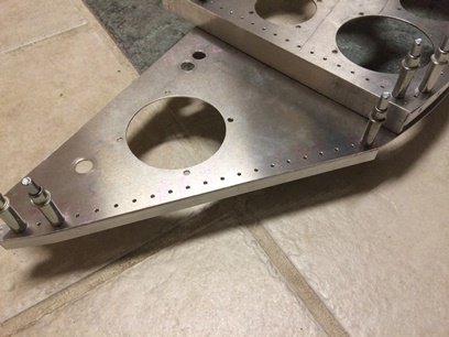
First... confirmed where I needed to drill the holes for the rivets on the vertical edges of the face plate; 1/8inch. 1/8inch, 3/16inch... 7/16 in from the sides of the face plate. Used one of my paper rivet drilling patterns... glued it on and drilled the holes (centering bit to start... #40 to finish). Deburred then clamped the "U" channel (after notching for the top "L" flange... which took a while) to the face plate and carefully match-drilled. Nice job !!!
Repeated same for the second "U" support. another... Nice job !!!
Deburred all the holes (except the damn opening inside of the "U" channel... need to figure out a clean way of doing that).
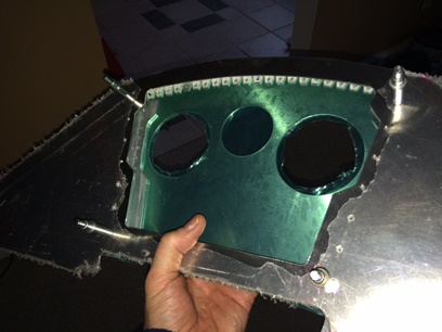
My point of view...
Ready for rivets.
Click on image for larger photo.
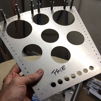
February 7, 2016 TEN panels...
Wait, how many do I need ???
Too many changes to make this work !
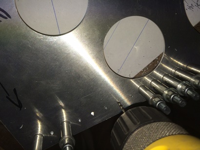
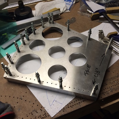
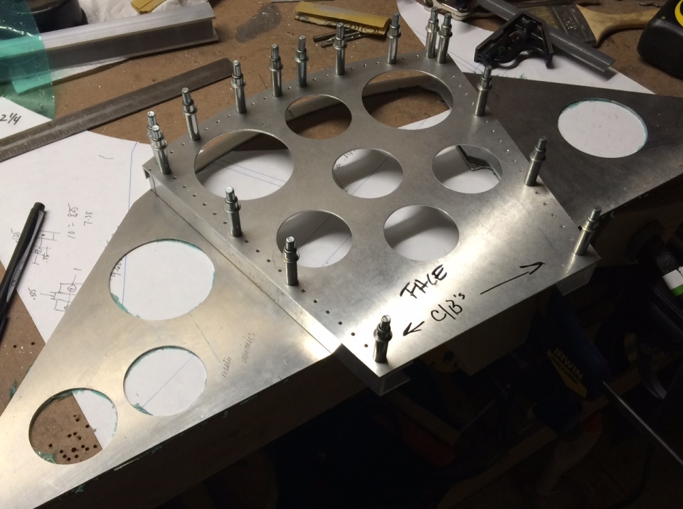
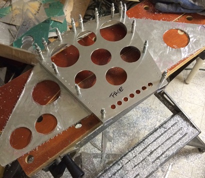
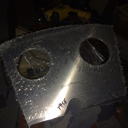
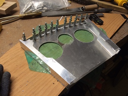
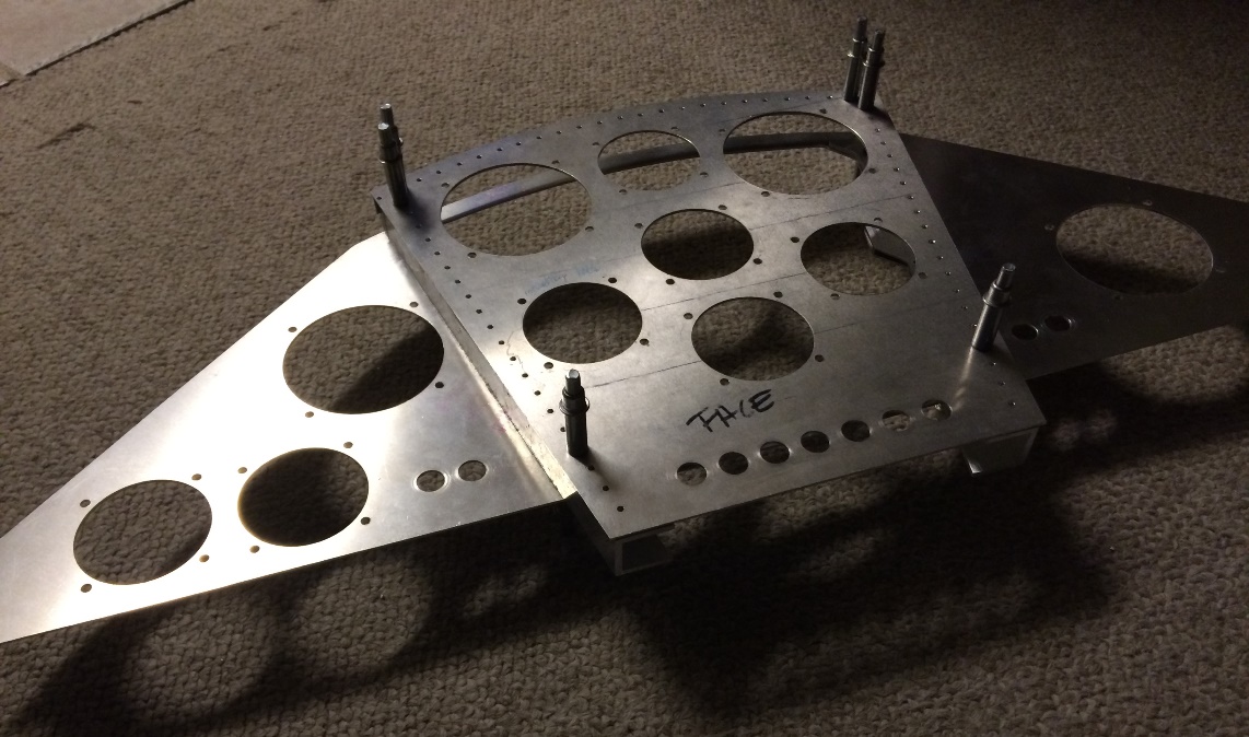
Started off today with figuring out and drilling the holes for the circuit breakers. Put seven 1/2inch holes in the back cockpit's face plate. Looks nice... I spaced them 3/4inch on center so they're pretty close, but, with an instrument panel in an airplane... you need to conserve space as much as possible.
Next thing I needed to do was figure out where I was going to drill the rivet holes for the rear of the "U" supports to the main panel. I've done a bit of modifications to the original "U" channels and where I was going to locate them on the main panel (big change was moving each of them in 1/8inch). These changes left little area for riveting to "U" channels to the main panel. A little over an hour later I decided that I needed to re-route all the work I did on this one too, including all six holes I drilled into each which took anywhere from 3 - 6 hours to do. It's something I have to do...
ok...
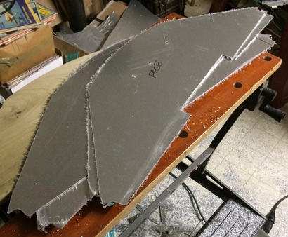
With that decision made I began the routine of cutting down the size of the 6061 T6 aluminum to managable sizes for each of the panels; two front pit and NOW two back pit panels. Everything the same as before but some how one of the back panel's panel shifted while I was routing it and I cut 1/8inch too much from the top starboard side... so make that five panels I had to route.
oh wait...
while routing the last panel (one of the front panels) I was thinking of how careful I was being so that I didn't screw this one up too. No lie... after making a pass with the router on the front pit's panel where I had screwed up the back pit's panel... I saw that THIS ONE SHIFTED SOMEHOW TOO !!! WTH ??? So... make that SIX panels routed for FOUR panels needed. oh wait... Make that TEN panels routed for FOUR panels needed.
Four good panels.
February 8, 2016 Two of each...
thought it was three.
Time to spend hours on cutting those holes... (getting metally prepared)
Put one of the new cutters on the adjustable hole cutter. It took cutting five test holes before getting it to the size I wanted. And once it was to the size... it only took about five minutes to cut each of the 2 1/4inch circles. Amazing what a sharp tool can do, eh ?
Next up... 3 1/8inch holes. I'm getting better at adjusting the tool... it only took three tries of adjusting before I got it right. From all the test holes I've been making it has dulled the blade a little; about ten minutes on each of these holes and I was finished ! Spent way more time measuring for location of holes, and adjusting the tool, than cutting the holes.
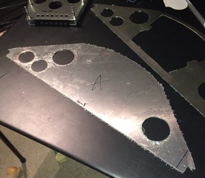
February 9, 2016 Each hole... each cut...
deeper into each step.
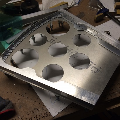
Back down to work on the back pit's main panel. Still need to cut the recessed opening on the panel and then figure out a few things before cutting more holes...
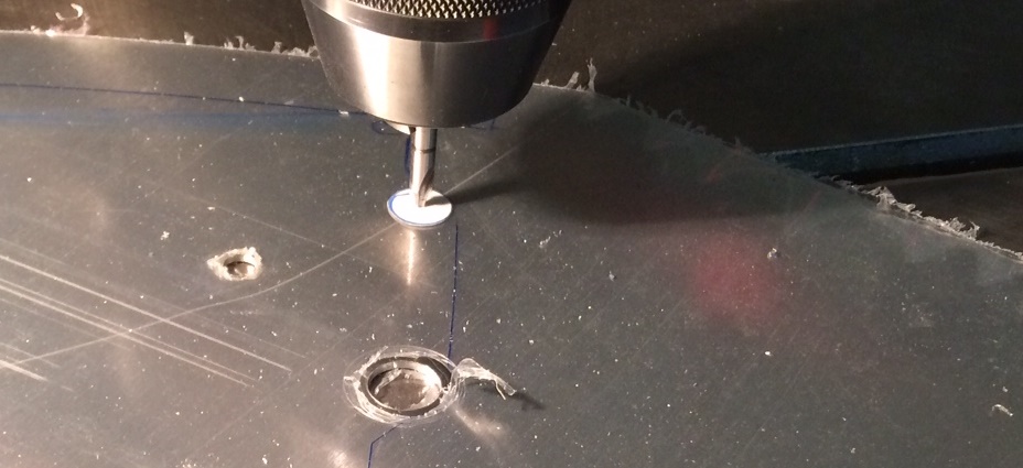
First thing... drilling the relief holes at the corners of each turn; 1/2inch holes should do it. Followed by connecting the dots with the saber saw. Made quick work of what was a lot of manual work the last time I did this!
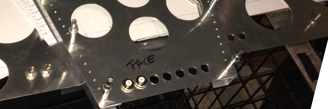
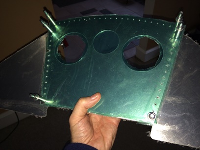
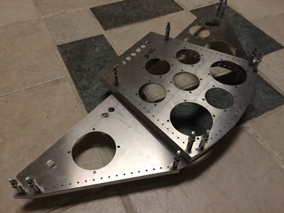
My last session for the day was to figure out (again) where I wanted to put these toggle switches... I think I have what I want and where right now. It's a coin toss... I may need to add a switch or two... and the number of curcuit breakers I have may be too many. I'll just mark as unused. BUT, I need to get these holes drilled before riveting things together. I know it will be a pain if I wait until after things are permanently together.
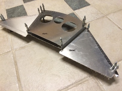
Here is what I have so far. I'll let it set for a day or two to see if more need to be added. If not... on to riveting things together AFTER I drill the mounting holes for the instruments.
Click on image for close up of toggles and cb's.
With each step into each of the pieces of the puzzle... I step more carefully. Not that I'm not being careful; I'm always making sure things are being done right and to the best of my ability. It's just, and I've said this before, the deeper you get into a part... you have a lot invested into it time wise... and you take a critical eye to each thing you do, more critical with each hole and cut that you make. I just want to keep in mind that I don't want to have that critical eye stalling the project.
February 10, 2016 The permanence...
of each step.
Backatit... again tonight. More work on the instrument panel; surprise surprise...
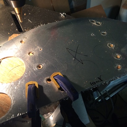
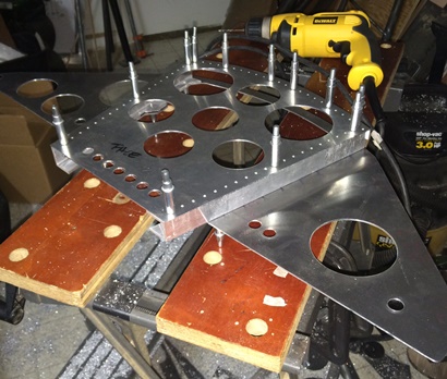
Goal for tonight was to drill the main panel, on the back pit's insturment panel, to mount the "U" channel to for permanence... I'd have this part completed tonight no matter how long I took to do it.
Kept the clecos in the face plate so as to keep things aligned for it... then aligned the mounted face plate onto the back/main instrument panel. Took a few measurements and clamped the two together. Took a few measurements and made an adjustment ('cause it moved slightly). Flipped it. Blocked it up. Started the to drill the first match-drilled hole with a little hesitation. Hole complete and cleco'd, I flipped it to check for alignment... all good.
Continued to slowly match-drill the holes and flipped to check throughout the entire procedure. Once finished I un-cleco'd and flied smooth the burrs inside of the "U" channel and used the deburring tool on the ones that I could reach.
One-point-seven hours; done !
February 11, 2016 Back to the one...
that started it all.
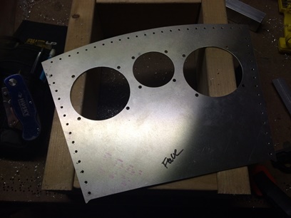
Back to the face plate that started me back down this road of re-do's; 2024 T3 is easily scratched... in my opinion so I've gone back and re-routed every (just about all of it) in 6061 T6.
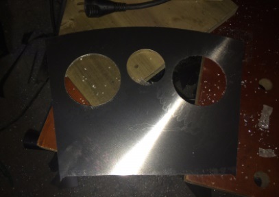
Tonight, back to the perpetrator of it all... the face plate for the front pit. Took one of my wrongly re-routed back plate "practice pieces" and match drilled to the wood template/jig and routed top and bottom... then clamped to a straight-edged piece of wood and routed the sides. Started marking for the holes and after a time saw that the centering hole for one of the two 3 1/8inch openings was going to fall partically on the hole I used to attach it to the template/jig. Ya know... it probably wouldn't have made a different because I clamp the aluminum to the drill press table and the aluminum is "soft" but... after all the other crap I've gone through in making these I decided to just route a new piece. And... so I did.
Back to the point of measuring for the three holes... the adjustable cutter was already set-up for the 3 1/8inch holes. Cut those out pretty quick even though the blade was getting dull (which I'll change for the 2 1/4inch hole). With both 3 1/8inch holes cut I call it a night. Tomorrow... the last hole and then everything else to catch up to the back pit's panel.
Still need to drill 2 1/4inch hole.
February 12, 2016 Still on the one...
that started it all.
Final hole for the main instrument panels? I hope so...
Drilled the last, and final 2 1/4inch hole for the front face plate. (yeah).
Back to repeating what I did for the back face plate; notching and fitting up of the "L" flange followed by final fitting of the "U" channels. Spent about an hour and a half on notching the "L". More tomorrow...
February 13, 2016 Sheryl Crow, Roy Orbison, Heart, Joe Cocker...
it's all good listening when working on the biplane.
Not side-to-side... but inside working out; the best way to match drill the flange to the top curve... (figured that out after the first one)
I just realized... looking at a photo that I took of the "U" channels on the front face plate, I'm saving weight by notching all these flanges and channels. Nice !
Spent the day listening to 4.5 hours of music... well, that and working on the biplane.
Trying to bring the front face plate up to speed to the back face plate. That way, I won't forget any of the mistakes that I made on the first one so as not to repeat them on the second one.
Made sure that I had good lighting... and I started working at match-drilling the flange to the top-curve of the front face plate. Ohhhh... I took my time and tried to get it as close as humanly possible; lining up the vertical edge of the "L" flange to the edge of the face plate.
It's Saturday... I have plenty of time to work on the biplane. Next up, drilling the spaced, rivet holes in the face plate for the "U" channels. The 1/2inch spaced layout I did for the seats (way back when) are working for a lot of the parts that I'm riveting... 1/2inch spacing works for everything ! 1/2inch, 1inch, etc. Well, not for everything, but you get the idea; just print these out, glue them on... set the distance from the edge and start drilling !
Face plate hole drilled I can match drill the "U" channels to it. Same as before; make sure that it's in the correct location, spring clamps to hole in position while I get one of the better clamps to make sure it doesn't move at all. Double... triple check things are in line and I drill the first match-drilled hole. Cleco, then check for alilgnment again... Drill the far off hole. then cleco. Position is now set in stone. If I'm a little off... oh well. But, it isn't, so all is good.
Finish drilling the holes for this side of the face plate then move on to the "U" channel on the other side. Lookin' just as good as the back pit's face plate; less holes but just as fine.
Still need to drill the instrument mounting holes... then check to make sure I haven't forgotten any other holes on it, then I'm ready to rivet these bad boys together. Oh wait... I still need to match drill the "U" channels to the main instrument panel in the front pit...
February 14, 2016 Kinda like...
yesterday.
MORE work on the instrument panels. (I didn't think that they would take this long...)
Today... mating up the front cockpit's instrument panel to the face plate. Did I learn anything from yesterday to make it easier today ??? No... it was pretty easy yesterday.
I needed to cut the opening out of the main panel like I did the main panel on the back cockpit's instrument panel. Marked and drilled the 1/2inch holes then connected the dots by cutting with the saber saw... then filing and sanding smooth.
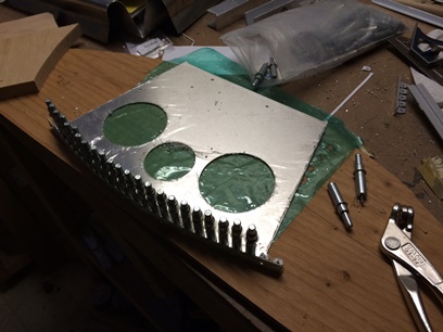
Glued on my 1/2inch, spaced printed patterns. Drilled and deburred every 1inch on center... then aligned and clamped the "U" channels (with the face plate attached) to the main panel. Checked. Double-checked. Triple-checked... then checked again for alignment. then... started drilling and checking for movement.
Note: Removable centering circle made out of paper.
February 15, 2016 IFR...
and drilling instrument mounting holes.
Put in quite a few hours tonight... since I was working out of the house I was able to jump right on the project at 5PM. Took a break. Got bored with the TV and headed back down to finish the job...
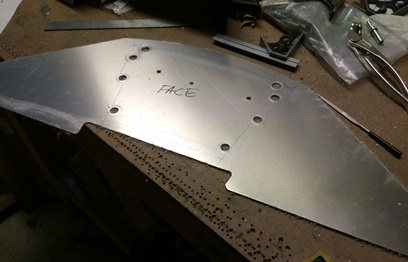
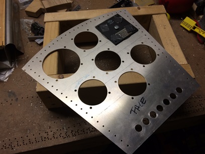
Figured it was time to drill the instrument mounting holes in these panels. Tedious... yes. But, a neccessary evil. If I don't, I ain't got nuthin' to look at...
Bought one of those fangled instrument hole drilling jigs from Aircraft Spruce. Works like a charm. They have it set-up for .177 drill, or #15, which doesn't make any sense since a #15 drill bit isn't .177. But anyways... I took Tony B's suggestion and used a .167 drill bit using the jig for guidance. Sure, the drill guide is a little over sized but take my time with the drill and I get it damn near centered. BINGO !
Drew lines on the face of the panel but that really didn't help. Even with a fine-line marker the line was still uneven in thickness and who knows if I line up the rule on both marks... making a line that's tilted. I checked (many times) each corner of the jig when in place buy using one of my adjustable squares. I'd leave the rule a little long and allow the rule to slide through the main part of the square until it stopped. Took note of where it stopped and then (without moving the rule) try it on the other corner of the jig. If it move... there was a difference between the two sides. I'd go back-and-forth until the rule wouldn't move whichever side I would start and end on. Took some time... but as you can see, it worked out great. The problem with the curves and the various height instruments is that even when you have the jig aligned right, it don't look right... kinda like flying in instrument conditions. Ya gotta put your life on what the instruments say and not what your head says.
Finished up the face plate and called it a night, or so I thought. Went upstairs just to take a break; veg out. Nothing caught my interest on tv and I didn't want to just jump on the computer and waste my time looking at nothing... so I clocked in for another session.
Back down to the basement workshop to drill the instrument mounting holes for the main panel. Went to insert the 2 1/4inch aluminum disc from the jig into the instrument hole and... it wouldn't go in! WTH ??? All that time I took making sure the diameter of the holes I cut would allow room for the instrument... and NOW... it's too small ??? WTH ???
Thought of and set up the drill press to cut the holes a little larger. Naaaaa... I can see that not working out of the gate. So... I decided to take a piece of 150 grit sandpaper and just work it around the hole slow and evenly. Took a little time but it worked like a charm. Should have made them all under-sized and worked them up to a fit by doing it this way. Maybe next time...
Both sessions... a little over four hours and I have all the instrument mounting holes drilled for the back pit's instrument panel. One thing more before I rivet them together ? Maybe ? Is the notch out for the altimiter. I can always do it later... but I'm thinking now.
Click on image for larger photo.
February 16 and 17, 2016 Busy...
but not too busy to work on the biplane.
I've been real busy for the past two days. My morning yesterday... when I usually update my blog, I was busy working up numbers for a project for work. So here I am squeezing it in with my update from last night.
The other night... spent .9hrs (yeah that's all) on the project (busy doing things that night too !). Drilled the instrument mounting holes for the front pit's instrument panel.
Last night I worked on the... instrument panels again. (There was a time I couldn't wait to start working on the instrument panels... so that I could see what the biplane looked like "fitted out". But I've made them so complicated they're getting to be very time consuming. I think I'm just beginning to see the light at the end of the tunnel.)
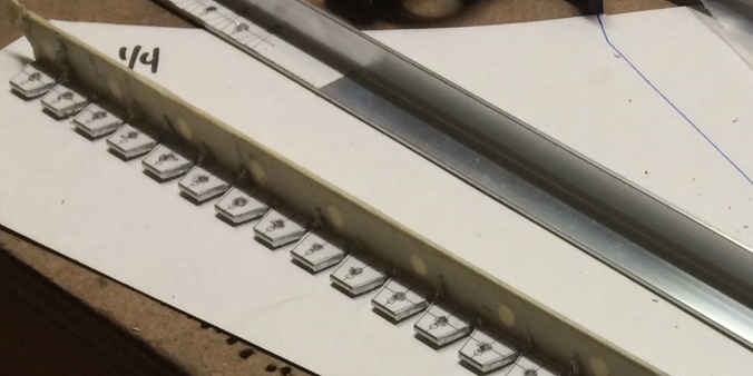
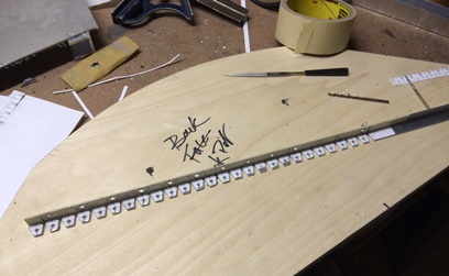
I need to make and attach the "L" flanges to the tops and bottoms of the main panels for both the front and back pits... the flanges that I will "tie" the pieces together with aluminum sheets to create the "box". First things first... I needed to drill the rivet holes in the "L" flanges. Took a four foot length of flange, glued on the drilling pattern and drilled and deburred away. Unlike most of the "L" flanges I've prepped in the past, I only needed to put in one notch for each section I was going to match-drill to the panels.
With a four foot sesction of "L" bracket drilled and deburred I was ready for measuring, marking and cutting the two pieces for the first panel. Placement of the flange on the panel was based on where I needed to put the bend; the section that I notched out. Both sides fell out neatly with 19 holes above the notch and two below. NICE !
Clamped a flange to the back of the panel and match-drilled the holes. Deburred after drilling all twenty-one. Second one... same thing.
Who doesn't want to see more drilled holes ???
February 18 and 19, 2016 Need more cowbell...
more like... need more flanges.
Not sure if it's... I'm just working too much at work and on the biplane, but I just don't seem to have the time to update this blog every day... or ? Maybe it's just so much of the same thing that I'm not writing anything new (aka... getting bored of the writing)... other than what I just did which was similar to what I just did the day before or the day before or the day...
The 18th: Match-drilled the straight "L" flanges to the front instrument panel's main panel. Same as... (drum roll) what I did the day before.
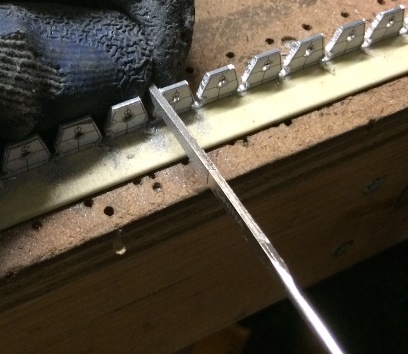
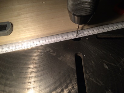
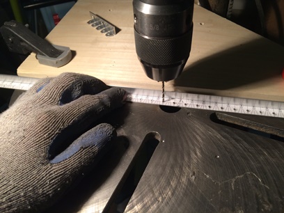
The 19th: Need more cowbell... er, drilled flanges. Spent the night center drilling marks then drilling through with a number 40 drill bit.
And yes... I know you're just dying to see another photo of a drill bit going through aluminum...