Mantua, New Jersey
Original Site:
September 2004
E-mail: usav8or@yahoo.com
The Radical Radial Driver's seat.
November 24, 25, 2016 Wait for it... wait for it...
BOOM !
The 24th... jigged up the fuselage for the depth of the first seat-back pan. Then... off to Turkey Dinner.
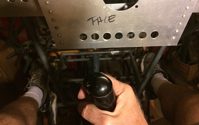
Next up!... bending these seat-back pans around the tubes of the fuselage. For that, I'll need to go back and remember what I learned doing that for the seat pans. The one be caveat I can recall... don't rush the process ! If I do, I'll scorch the aluminum and I'll need to cut a new blank and start out all over again.
As a reminder... you start off coating the area to be bent with soot (light the accetylene gas on your welding rig for sooting)... you then slowly burn off the soot with your tourch flame set as if you were going to weld (when the soot starts to disappear it's ready for bending). Remember... this is a slow process. Wave the flame over it, and up and down the length of the bend. I used my 201 tip for the smallest flame possible... for the slowest heating up of the aluminum possible.
To bend the aluminum around the tubing I use a VERY THICK
pair of welding gloves. I'm talking THICK ! The light leather
gloves I like using when I'm welding arn't thick enough for
this job.
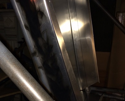
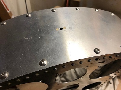
Application of soot.
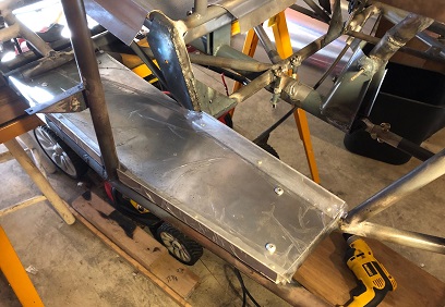
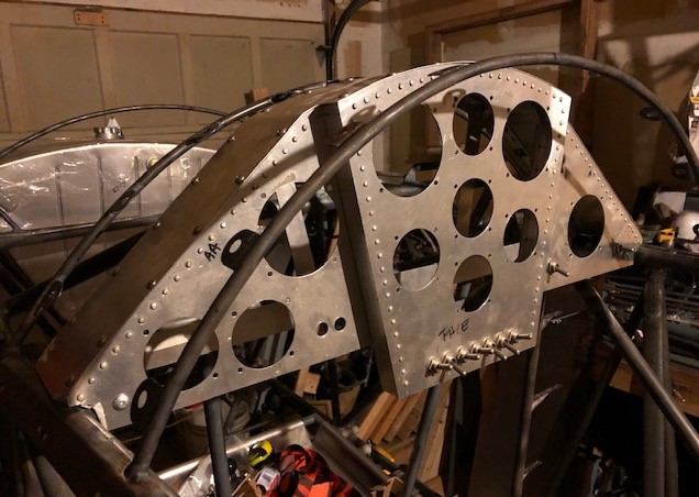
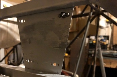
Fine looking seat-back !
Ready for the second seat-back...
November 26, 2016 Wait for it... wait for it...
Ba BOOM BOOM !
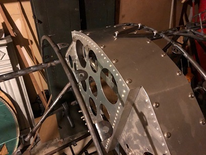
Getting the second seat-back pan ready for wrapping.
A lot of glue to take off of it... used M.E.K. Not nice stuff... went outside where there was a breeze. Used thick rubber gloves and avoided breathing the stuff in. After all said glue was removed I still needed to file the rough edges of the piece.
Okay... ready for bending... opps, not yet. Still need to file the slots at the top-back to allow it to go beyond the vertical tubes that support the battery tray. First try on that and I didn't make enough of a downward cut... second one was a charm.
Now... thinking this through a little bit more, I'll need to cut down the upper wrap to miss the tubes (or least I think I do). I'll need to check this the next time I go to work on the project...
December 2, 2016 Just when you think...
Ba BOOM !
Over the past few days I managed to wrap the pilot's seat-back pan... and then decide that it ain't gonna work out the way I wanted it to. So... I have one option... but some others may think you have two. The two being... modify the existing to MAKE it work, or, start again. Don't get me wrong... it looks great, but doesn't work as I had planned it to.
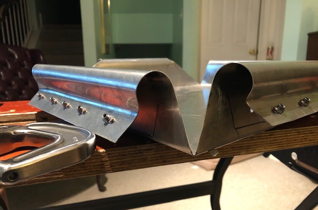
And start again I did... Looking at the existing seat-back pan I discovered that the wrap needs to cover the vertical tubes entirely, top-to-bottom. The existing seat-back cut the verticals into three sections. My thought... somethings going to catch on those edges and either rip whatever catches on it or will bend the aluminum. Either case... not good. Although the wrap needs to cover the front edge of the tubing it can't wrap the entire piece top to bottom. Approximately 6inches of the top and 7inches of the bottom will be fully wrapped and riveted. The top and bottom edge of the seat-back pan are fine.
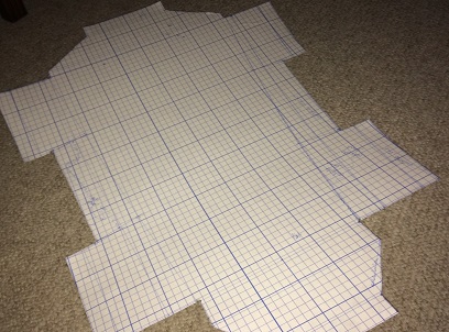
Pulled out the computer and fired it up. Made the changes to one of the CADs I had and then started hand-drawing it on paper. Right now I've got the aluminum blank cut out close to the pattern. Only need to file, sand, bend, anneal and wrap...
oh... I was out of .o32 5052 aluminum so I needed to take a drive over to Fazzio's to pick up another 4' x 10' sheet and stuff it into the Challenger.
Great looking... but doesn't work like I wanted it to.
New seat-back pan.
December 3, 2016 Yeah...
always Jimmy John Fast...
the second, third... time 'round.
One of the nice things about a re-do is that it gets done a lot faster... well, not really if you're counting the first and/or second attempt at making that piece. Anyways... you've learned from the first time(s) and you're improving on the product that you are making.
The seat-pans I made paper patterns for it... not so much for these seat backs. Maybe I should have... maybe it wouldn't have matter... I think it would have though. I wouldhave seen that weird twist that the back seat-pan back would have had to make on the upper wings and maybe would have noticed that the 3-section sides wouldn't have worked either. We live and learn and that's what this is all about.
Made short work of cutting out the pattern. Actually made a modification to the above cut-out that I had made to the others... angling the cut from the bottom of the seat-back to the tab at the top of that side. Also angled the sides instead of the straight cut.
With the pattern cut-to-size I set about bending this one up. It's ready for filing those slots at the top, like the first one, then annealing and wrapping.
December 4 and 5, 2016 It's not...
always Jimmy John Fast...
the second, third... time 'round.
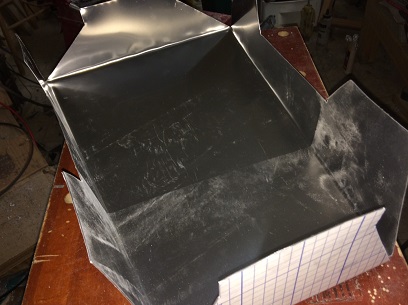
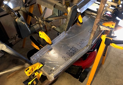
Wasn't as easy as the other pans to wrap... but I'm REAL close to having the back seat-back pan wrapped. Just one or two more minor tweaks need to be made to it.
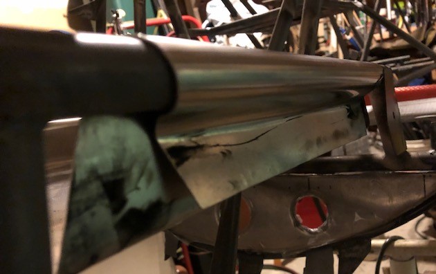
There's several tubes that criss-cross near the vertical tubes for the pilot's seat back. It doesn't make for an easy wrap.
My initial wraps were made in place, on the spot that the seat-back would be attached to. I needed enough bend on the top and the bottom of the wrap so that I could position it on another tube. That tube was a 3/4inch tube just lying around the shop. I had to do this because the criss-cross of tubes kept me from fully wrapping the seat-back pan onto the fuselage.
I did my best to anneal and wrap the sides on the "loose" 3/4inch tubing, but it needed additional tweaking once I put it back in place on the fuselage. The fit ain't perfect but it's DAMN close. Looking good too !
Okay, so it's on the fuselage now... and looking at it I see that I need access to the battery tray right behind the seat-back. Thinking... I can either put a large access hole, with cover, in the seat-back or, make the seat-back pan removable. Making it removable will allow me to have a large access hole for working with the battery AND everything else in the back part of the biplane. It'll be a little bit more work to make the entire seat-back pan removable but in the long run will make it easier on me.
I plan on doing this by using anchor nut plates with nuts instead of riveting the back in place.
December 6 and 10, 2016 Always...
thinking...
ahead.
Wasn't feelig like doing much on the build over the past few days... had a chest-cold and took it easy. Didn't stop me from thinking about it... and thinking things through.
I'm pretty good at getting things made and then just dropping them right there... before figuring out how they're going to attach to the fuselage. Not with the seat-back pans. I know that I'll be attaching the seat pans with rivets; they won't need to be taken out once attached. I thought the same about the seat-back pans until I thought it through... the battery is going to be just behind it. Because of the shape of the fuselage (with the stringers) I can't put an access hole in the side... it just ain't gonna work. So I figure I have two options; put an access hole in the seat-back pan, or, make the seat-back pan removable. The access hole will only give me a limited amount of room for working... removal of the entire seat-back will give me so much more room for working.
I make the decision to make it removable. I'll rivet anchor-nut plates on the tabs and use number 8 machine screws for attaching. Now it's just a matter of making the pattern for drillig the holes after figuring out the placement of those holes on the bottom of the seat-back pan. The back of the seat-back pan rests on two vertical tubes (which will take most of the weight when pushed on with "G's". I'll secure with four screw on each side, top and bottom. The top will clip over the top tube and the bottom tab will attach with screws into the seat-pan.
by the way... I just hit 4000.6hrs
December 11 and 12, 2016 I didn't...
think...
ahead.
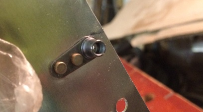
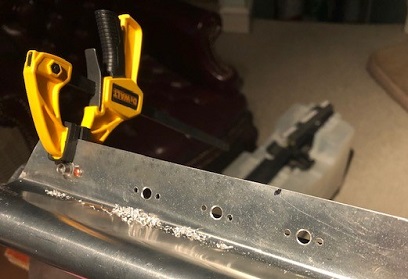
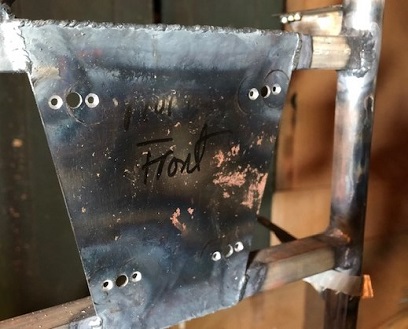
Working on getting the anchor-nut plates attached to the back-seat pan. Drilled and deburred the holes for the rivets the first night. The next night I was determined to rivet all sixteen anchor-nut plates onto the seat-back.
I started working on it and said DAMN ! I was used to riveting on the anchor-nut plates with two arms. The two-arm plates weren't easy-peasy when I was riveting them on... but when I saw what I had to do with the single-arm anchor-nut plates... it turns out they were very easy-peasy. With the singl-arm nut plates I need to align the nut plate with both rivets. But... since the rivets are close to each other I needed to pull the one out so that I could begin the squeeze on the first, but first I would need to tape the anchor-nut plate into position so that it wouldn't move too much, half-squeeze the first rivet, put the second rivet in, put a small clamp on the head of the nut-plate to make it flush with the aluminum, and then half-squeeze it, then finish squeeze the first one then go back to the second and finish squeeze that one. Esssssssssssssssh !!!
Actually, once I figured out what I had to do, it wasn't hard... but it was time consuming. Took me just about two hours to squeeze 32 rivets/16 anchor-nut plates. It wasn't that I didn't think ahead before doing this... it was just a different technique for riveting them on.
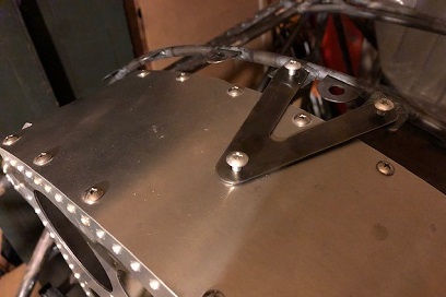
First one finished.
December 26, 2016 Still...
working it.
Spent a little over an hour today working on the front seat-back pan. I'd like to make it removable... but not sure now. Whatever I do, removable or riveted in place, I needed to bend the tabs about 15degrees for doing whatever.
It was a pain in the arse; anneal then take the hand-seamer to bend, repeat repeat repeat. Got it close to where it needs to be. It's a pain in the arse putting on and taking off for just the trial fitting. I'm thinking I'll need to wrap the tubing with something after I paint it so that it doesn't get damaged while re-installing it.
Decisions... decisions...
May 31 and June 2, 2017 Things are getting a little...
twisted up...
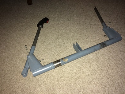
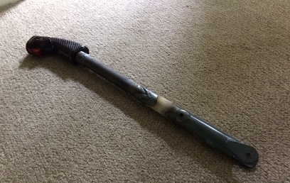
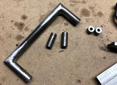
Started looking at the control sticks again. I have two stick grips... both different; one is a NAF 1173-2 and the other a Mason 81579 701-1401. The Mason has a nice feel to it but no real way of connecting it to the control stick. The NAF 1173-2 is just badass... comeon, it's the type that was used on the Navy F4U's and F6F's.
Decided the best thing to do is go... BADASS ! Needed to make a bushing that would fit the 1 1/8inch hole in the NAF grip and also slip over the 1inch control stick. Had been thinking about this before and had 1 1/8inch tubing (used in another part of the project) that would work beautifully.
Cut a length of that off the 8ft piece I had. Fitted and cut to length the piece that would slid into the Grip.... center drilled the hole for attachig the grip. Tried it on the 1inch control stick. Cut the 1 1/8inch tube to length. Stuck it on the rear stick socket and made a few airplane noises.
A few trial fits back and forth to make sure that I had plenty of room between the grip and the control panel and still keeping to the plans of having the control stick in the stick socket 2inches. Also made sure that it felt right while sitting in the plane... which meant that it has a slight twist to it so that my hand wouldn't be cocked while holding it in flight.
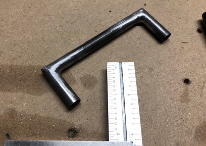
Cut to length, and with the known twist set in it... I needed to cut the 60degree fish mouth cuts in the stick socket for welding. Cut those by hand with a hacksaw... didn't want to screw things up trying to make quick cuts and having to make a new stick socket ! Fired up the O and A rig and welded on the top bushing to the control stick and the stick to the stick socket.
Finished piece...
Twisted grip.
June 3, 2017: Not a lot of time spent on the project today. It's Saturday... go figure. Busy with mowing, etc.
Decided to make the front control stick permanent. Marked and cut the 60degree V's in the stick boot. It's ready for welding.
May 18 and 19, 2019 Taking care of...
the "easy" stuff.
Back on the flooring. Opened the holes in the floor tabs for a #10 screw. Deburred and decided to use Monadnock clip nuts instead of anchor nut plates on the tabs
Not much room for riveting the anchor nut plates onto the tabs. I also deicded that I'll be using the minimum amount of screws to hold the flooring in place. The other tabs are good for support, but why add the extra weight of un-nescessary screws and nuts?
Monadnock clip nut
January 11, 2020 A burning itch...
from hell.
"Once again I hear somebody who is going to settle down and do their work, painting or writing or whatever, as soon as they get a better light installed, or as soon as they move to a new city, or as soon as they come back from the trip they have been planning, or as soon as... It's simple: they just don't want to do it, or they can't do it, otherwise they'd feel a burning itch from hell they could not ignore and 'soon' would turn quickly into 'now.'" - Charles Bukowski
Again... more thinking than doing this week.
Although, I did spend time on thinking about the "P-47" scoop design... drawing those thoughts out on the Delta CAD program. Thinking of sheet metal for the forward part (where there's sheet metal under the belly, and then possibly creating the back of it with stringers. Yeah... that's where I'm at with that now. Although, thinking about it now, this should be put in the fuselage section, not the accommadations.
But! I did do work on the "accommadations". Back to the seat pans and backs. They're there! They're made! I just need to work them now to be able to put anchor nut plates in them so that I can secure them to the fuselage.
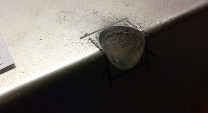
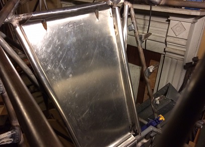
Took the ol' A/O torch and annealed, or should I say, re-annealed the four flanges on the seat pan for the pilot's seat. Crafted up a wedged shaped piece of wood. Snapped the seat pan back on the frame and then wacked the wedge up under where the flange curved around the tubing (the first time I did it they weren't wrapped around the tube enough to allow the flat part of the flange to sit flat).
Also... something I learned after finishing up the first round of annealing. It was when I was making the curved ends on the main fuel tank that I learned that you don't need to work the aluminum when it is HOT. It can be room temp and you still have PLENTY of time to work the aluminum. The more you work it the harder it will get. And, I think, after a day or so it will go back to its normal state (don't quote me on that). Not knowing that you could do the working after it cooled is one reason why they weren't bent all the way... I had to put on my heavy welding gloves (not the ones I use for A/O, but another pair probably four times as thick) to try wrapping the flanges when they were HOT.... by just using the gloves to squeeze the aluminum around the tubing.
All four are now bented/curved to close to what they need to be. A little tweaking and they are ready to be drilled for the anchor nut plates
Port side seat pan flange - proper bend.
Click image for larger photo.
January 17, 2020 Movies...
without the popcorn?
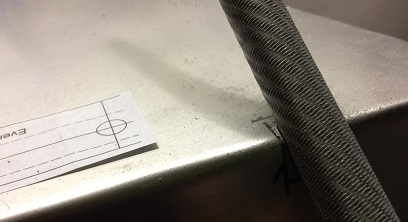
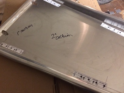
Next up... making this seat pan able to be attached to the fuselage.
Wasn't a problem, just a matter of the passage of time. I've done it before... holes for the screws, match-drill the holes for the anchor nut plates, and then riveting the nut plates on.
What was nice about the "no thought involved" was that I could be upstairs in the living room when doing the match-drilling and riveting. Gave me a chance to watch a few plane and war documentaries; F-105 Thud, and The Chosin Reservoir (the battle on the east side of the reservoir - Korean conflict). I wanted to watch "Battle For Sevastolop" but it was all in Russian and in sub titles. Kinda hard to read and work at the same time.
by the way... did I ever mention that I LOVE that Black and Decker Benchmate!
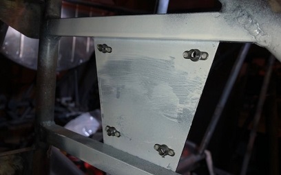
Riveting on anchor nut plates.
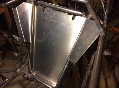
Pilot's seat pan ready for action.
Click image for larger photo.
January 18 - 24, 2020 Six holes forward...
eight holes back?
Wow! Seriously?
I spent four days this week on making a few holes and filling in a few holes. P E R I O D !
Another loose end that I wanted to tackle... attaching the instrument panel to the fuselage. The brackets are there, I just needed to countersink the holes and squeeze a few rivets to attach the anchor nut plates.
Simple... right? Wrong.
It was a pain in the ass getting the tool to the rivets holes on the side brackets to counter sink them. That should have been my first clue. The second clue... I couldn't get anything in close to those brackets that would allow me to squeeze or bang in a few rivets; hand squeezer? NO!, air-powered rivet gun? NO!, a good ol' hammer and bucking bar, bucking bar? YES! hammer? NO!. DAMN!
Okay, looks like I'll need to use just plain ol' nuts to put onto these machine screws for the side brackets. The top bracket... easy peasy. Took me 30 seconds to counter sink those four holes and a few minutes to squeeze the rivets to attach the nut plates.
I didn't want my learning mistake to show so I squeezed a few rivets with pliers (not pretty looking at first) and then filed the shafts of them (they look pretty now). Once it's painted ya won't even know that there was a learning curve there.
January 25, 2020 One hole...
er, make that three holes
Again...
Wow! Seriously?
Today I wanted to put the hole in the top of the instrument panel for the connecting bracket... ya know, to keep it from moving, and then start the next project.
Thought the other night that I couldn't rivet on an anchor nut plate so almost sucumbed to figuring I'd just put a nut and bolt there... then I started playing with things. Using a different jaw on the rivet squeezer. Trying various heads on the top and bottom of the jaw to see if I could get this in to the rivets to squeeze them... before I put the holes in there for the rivets.
It turns out that if I use the jaw with the deep throat... turn the adjuster all the way back to give maxium clearance, take the one head off before I angle it over the edge of the back part of the instrument panel... and then attach the head and turn the adjuster back to the close to right height I could squeeze the two rivets.
It took me 1.2hrs to do just that... squeeze two rivets to attach the anchor nut plate to the top of the instrument panel. The issue I was having was adjusting the height of the adjuster. It JUST WOULDN'T TURN!
Never got to the "and then start the next project..."
January 26, 2020 It ain't finished...
until it's mounted on the biplane.
It appears that I've left a lot of the little shit just hanging... a lot of the mounting for several of the pieces that I've made. I think my thought process was... "it's made, put a check mark on it, on to the next project." While in reality, I still had an hour or two left on each of these "finished" projects before they are actually finished.
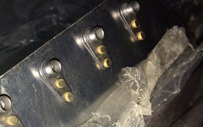
Case in point, the throttle mount plates. I designed, crafted, and welded these puppies onto the fuselage, BUT, I didn't rivet on the anchor nut plates (maybe at that time I was thinking I'd just use bolts, but the bolt is in a hard to reach area). Anyways...
I spent 3.2 hrs on match-drilling the holes, counter-sinking the holes, and then riveting on the eight anchor nut plates. Yeah... quite a few hours put on the project AFTER I was finished with it.
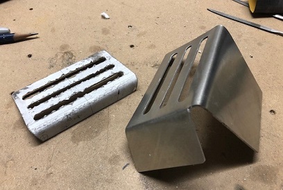
May 2 - 9, 2020 One throttle quad cover plate coming right up...
aka... what others are calling a toaster.
I was on a roll with writing... and originally put this in where I was writing about the fuel valve installation. I'll copy what I wrote here... then continue on with it.
A little back-story: I was waiting on the drill bits to drill the holes for the roll pins on the extension tube for the fuel valve system...
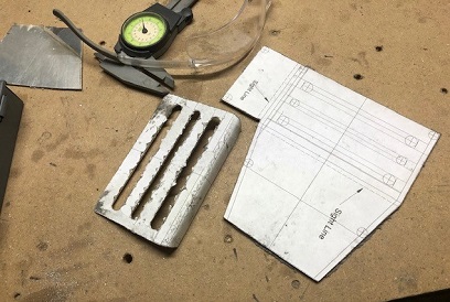
Plan "B" for today is to design and CAD up the throttle quad cover. I wanted something simple and light, something that I could put verbage on to let the pilot know what lever was for what... and what it did when you pushed or pulled it (also an FAA requirement). DONE and printed out the layout for making it.
Next day, glued that pattern on a piece of .040 aluminum and cut/drilled/filled/sanded start to finish. NO JOY! Although the slots I cut for the levers are in the correct location, I cut too much off of the front panel and didn't take into account where I needed to connect it with the existing bolts going into the throttle quad. okay... I'll re-design and make another one (the first one took me about 4.2hrs)... it's all about the learning, right! Re-designed it .25inch wider and put a side panel on it... and then printed out the pattern... glued it up and cut/filed the blank to shape.
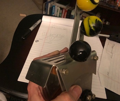
Next day I did all of that stuff I did to the first one (but now on a piece of aluminum .070, I was going to just plow forward and use the same pattern but thought that I'd better check before moving forward... checked the difference between the bend allowance and set-back of the .040 and .070 and it was only fractions of a fraction of an inch)... but didn't cut the front off. Spent an hour, that I didn't record in my log, taking apart and then putting back together one of the quads to make sure that the cover worked. Perfect! I match-drilled the holes in the throttle quad to the cover plate...
May 10 - 16, 2020 Okay, a little craziness...
a 2.8hr project?
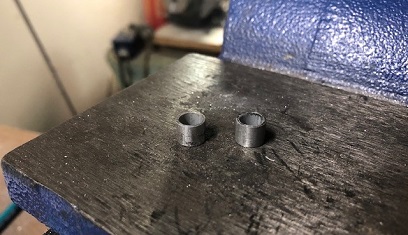
Two small bushings are all I made... just two.
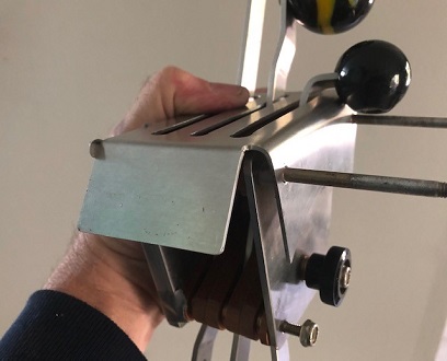
Had the throttle cover on the throttle quad and took a measurement for the bushings. Lathed down two bushings from aluinum fuel tubing... also tweaked the cover so that it was at a 90 degree angle instea of 95 or 100 degrees.
Disassembled the entire throttle quad (which ain't an easy task), inserted the bushings and reassembled the throttle quad (which ain't an easy task)... they're a little too long. When I tweaked the angle to 90 degrees it changed the space that needed to be filled by the bushings. (uhhh... yeah). Okay, so I take the measurements, and then disassemble the throttle quad again (which ain't an easy task), lathe down the two bushings, reassemble the throttle quad (which ain't an easy task)... and WA! LA!, perfect fit. The levers are all centered in the slots... just what I was looking to do.
Apparently "which ain't an easy task" takes about 2.3 hours to do.
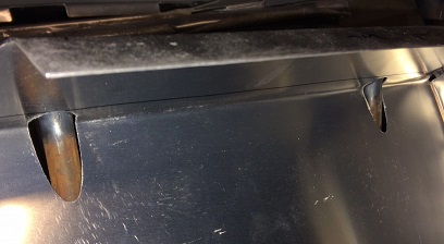
Looking at the "Punch List" I see that I need to come up with something that will hold the straps of the seatbelt harness; both the shoulder harness and the crotch-strap...
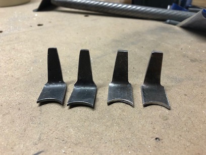
Mission accepted: Came up with two L-hooks for the shoulder harness' and a drawer pull-looking "catch" that will keep the crotch-strap from laying on the floor of the cockpit, and to make it easy to reach when sitting.
Easy enough to make the L-hooks. Although, the first set I made I wasn't entirely happy with. Made nice looking hooks, then discovered that the ends of the harness didn't sit so nice on them so I modified the ones I made (bad mistake as always) and... not liking the outcome. Made a modification to that design and made two new ones. YES! Figured out where I wanted to have them and then welded them in and filed the welds smooth (which I wouldn't do on a structural weld).
The two on the right are keepers!
For the crotch-strap catch, I could have gone to the hardware store and bought a $2.00 drawer pull... NOT! If for no other reason than I would have known. And, a drawer pull on my biplane? NOT!
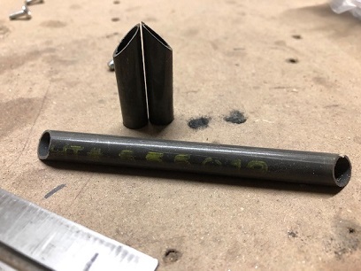
so.... four hours: Cut the tubing, welded it up, and filed it smooth (it's not a structural part of the plane... you wouldn't do this to a structual part of the biplane). I need to attach it to the seat pan somehow... cut, lathed square, and drilled/tapped four (I only needed two) inserts.
Originally thought that I only needed to glue the inserts into the tubing... then thought it out a little more AFTER making the first set of inserts (which were only 1/4inch long). Decided that I wanted to also put roll pins in them in addition to glueing. So... I remade the two inserts again (cut, lathed square, and drilled/tapped) but made them 5/8 inch long. They're glued in. All I need to do is drill and insert the roll pins (I need to purchase these still from ACS).
June 22, 2020 DAMN!...
just keep making things hard for myself. :)
okay... it all starts with a vision
I've had the layout of what the sides of the rear cockpit were going to look like for a very very very long time. I've had it cutout sitting on the fuselage. I've gotten use to that, um, maybe we can call it a "racer's look."? I like it. I'm kind of "stuck" with liking it. Actually I've tried to force myself off of that "facebook blue thumbs up" for awhile now. But... I can't shake it.
Lowering the sides will do a few things. 1. Pro: Keep me from having to figure out how to make a door to lower the side sheet metal 6inches to the upper longeron. Making it easier to get into and out of. 2. Con: Not liking the look of the lower cockpit sides. 3. Con: Force me to change the location of the faceted windshield. 4. Pro: Keep me from figuring out how I'm going to make this door work good and look good. A learning curve. (wait... did I mention that already?)
But me with my "vision", and a good one at that... must move forward with making THAT vision happen. So... I'm in the process of figuring out where and how to make the small opening on the port side of Big Ass Bird. It has to be light and simple. Nothing too complex. And I don't want to add much weight.
I've been going through a few trials and errors to start with... before launching into a full attack-mode. My first thought was to have something that looked like the side enclosures for the back of the biplane; a solid piece with lightening holes, but that didn't go along with the rest of the framework of my build. I think it would look out of place. Next would be to weld a 3/8inch .028 tube onto the top longeron (which I originally thought that I couldn't that's why I had thought of my previously mentioned idea) and proceed from there. On looking at it again... I was right, the area that I would need to weld would be on the outside edge of the top longeron... not where I want to be welding.
So, how about melding the two together; the light-weight 3/8inch x .028 tube with a bracket to attach it to the top longeron, then weld tabs to that for anchor nut plates that would allow me to do what I need to do with the door. Right now... I'm at that stage of development. We'll see if it's a deadend or not. Stay tuned!
Apparently "which ain't an easy task" takes about 2.3 hours to do.
Looking at the "Punch List" I see that I need to come up with something that will hold the straps of the seatbelt harness; both the shoulder harness and the crotch-strap...
Mission accepted: Came up with two L-hooks for the shoulder harness' and a drawer pull-looking "catch" that will keep the crotch-strap from laying on the floor of the cockpit, and to make it easy to reach when sitting.
Easy enough to make the L-hooks. Although, the first set I made I wasn't entirely happy with. Made nice looking hooks, then discovered that the ends of the harness didn't sit so nice on them so I modified the ones I made (bad mistake as always) and... not liking the outcome. Made a modification to that design and made two new ones. YES! Figured out where I wanted to have them and then welded them in and filed the welds smooth (which I wouldn't do on a structural weld).
The two on the right are keepers!
For the crotch-strap catch, I could have gone to the hardware store and bought a $2.00 drawer pull... NOT! If for no other reason than I would have known. And, a drawer pull on my biplane? NOT!
so.... four hours: Cut the tubing, welded it up, and filed it smooth (it's not a structural part of the plane... you wouldn't do this to a structual part of the biplane). I need to attach it to the seat pan somehow... cut, lathed square, and drilled/tapped four (I only needed two) inserts.
Originally thought that I only needed to glue the inserts into the tubing... then thought it out a little more AFTER making the first set of inserts (which were only 1/4inch long). Decided that I wanted to also put roll pins in them in addition to glueing. So... I remade the two inserts again (cut, lathed square, and drilled/tapped) but made them 5/8 inch long. They're glued in. All I need to do is drill and insert the roll pins (I need to purchase these still from ACS).
July 4, 2020 Pretty wins out...
over functional. As always!
HAPPY INDEPENDENCE DAY!
I've been kicking so much butt on BIG ASS BIRD III that I haven't had time to update the BLOG... literally. I've been putting in HOURS on it!
okay... so I'm thinking, door, or side supports to support the coaming around the pilot's cockpit... to stiffen the coaming for getting into and out of the seat. Actually I didn't have this thought until working through what you'll read below.
I started thinking that I need to put a small door on the port side for entry and exit. The height of the coaming was pretty high. So I started making various "door jams" for that area to begin the process of creating the door. All of this was just "shooting in the dark". I wasn't exactly sure how I was going to enter and exit the cockpit... at that time it was sitting flat on two saw horses. I finally decided that I needed to set the fuselage up in a "real world" setting. I took one complete night setting up the fuselage as if it were sitting on the tarmac ready for me to get into it. This put the top of the firewall at 80inches above sea level (and from that I can estimate the tip of the nose bowl will sit at 103”). And that is pretty frickin high.
This allowed me to experience what it would be like to climb into and out of the cockpit. There is a major difference between what I thought it would be like and what it was like. A few notes: 1. The hole opening was a lot smaller than what I thought it was. 2. It was nearly impossible to lift my trailing foot (the second one over the coaming) over the coaming without dragging it over the side. And I'm pretty athletic. 3. I wasn't happy with how high the windshield sat with the opening at that height.
I did this experiment AFTER I had made a few variations of door frames for a small door. I won't go through all those permeations because... in the end I didn't use them. If I had been keeping up with my BLOG you would have seen those posts... you can check out my Facebook page for those daily post and see what trials I went through.
Okay... decision had been made to cut-down the sides of the cock-pit by 5inches. This allowed me to lower the windshield's angle to a nice "racer look"... we'll see how that works with the wind while flying. I've seen one or two biplanes with screens at that angle with no wind problem. With the sides of the cockpit cut down... the door would now be pretty damn small... almost a waste of time figurig out the design and build of it. Plus, it would mess up the look of the biplane. Not to be sexist... but it's like a woman wearing 4inch heels, because it looks good, and puts up with the harsh reality of how uncomfortable it is to walk in them. Vanity trumps practicality almost every time.(I'm not doing much to champion my descsion, eh?)
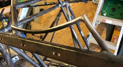
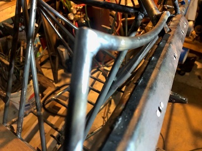
With a small coaming still around me... I can't get my elbows onto the upper longerons to hoist myself out of the seat. So... I researched photos of pilots gettng out of their cockpits. What they are doing is putting their elbows outside of the cockpit and lifting themselves out by using the coaming as a support, aka lift handle. I guess that it will be strong enough, from what I see others doing, to support your weight repeatedly... but, I decided that I would create supports to help relieve some of that pressure. Not an easy feat since I'll need to have the horizontal span of the support follow the curve of the opening and then support that tube with two that will be coming off the top longeron without having to cut into the metal strips I have along the sides for attaching the skin to.
Pulled out my good old circular forms for bending tubing and bent the two horizontal pieces to shape pretty quickly. The front tube for the support wasn't a problem... I'd just notch it to fit on the inside of the upper longeron instead of attaching it dead top-center. I decided to notch the rear tube to fit the angled tubing that I had put in that lifted my seat belt sholder guides. Both of these tubes were more of a problem to make than the curved pieces. After notching the starboard side, I made patterns from those tubes to grind the shape on the two port-side tubes.
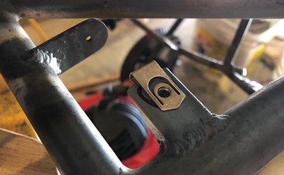
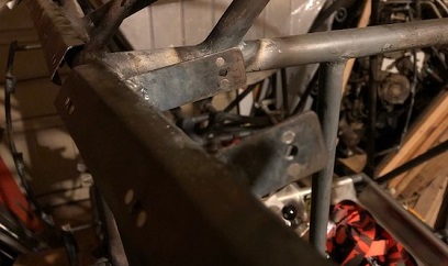
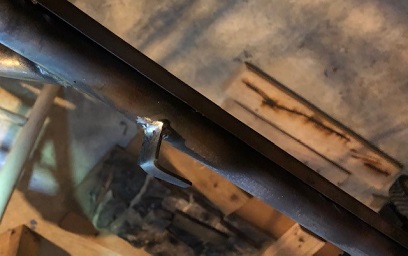
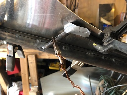
A royal pain in the ass postioning the front tube to tack it in position. I needed a third hand. I FINALLY came up with a plan to tack on a bent piece of welding rod (a flat tab would have been better) to the tube that I would grind off later. I have a large clamp with a long copper wire wrapped around it with an alligator clip attached to the far end. Clamped this to the side of the fuselage, bent the wire so that the tube was in the correct postion... taped the top end to the horizontal tube... and then tacked the lower end in place. Easy peasey... once I figured it out.
Clip attached to temporary tab to hold tube in place.