Mantua, New Jersey
Original Site:
September 2004
E-mail: usav8or@yahoo.com
more work on the...Radial Fuselage.
December 16, 2014
Lots of hours...
little to show...
Recently I've been thinking about all those brackets that I need to make and attach before sandblasting and painting the fuselage. My issue is... what do I need to attach and then where do I need to attach it and then... what type of bracket do I need to make for it.
I've written them down on paper several times. Each time I write down the list it gets longer. I've got to stop writing and start doing.
So... I've got to choose one to start with and I figured I'd make it the battery tray. The Standard Skybolt's plans clearly show where to place the battery and what to make it out of (or at least what tubes to use to make the support frame for the battery box). Gives you two options depending on what size engine you're going to use. The Radial Skybolt's plans... not so much. I search the plans and only when I compare the two do I finally see what appears to be the battery placement and what tubes are to be used. Their ain't a whole lot more than a side view of the shelf. Not complaining... but that's all there is. Not much more on the Standard's.
So. Now I want to make sure that this is close to where it needs to go. I'm thinking that I could contact Steen to see what they were doing with the Model 14. But... they haven't worked on that for years and I'm not even sure if anyone would have knowledge of it. I needed an answer relatively quickly so that I could continue moving forward. The Pitts Model 12 has been built in numbers and the Kimball's know their stuff. If I can confirm that the location shown on my Radial's plans (or at least what I think it shows the locations) is close to what the Model 12's is... I'm in business.
There's a sight out there called 2Wings, which can be found at www.2wings.com... it's got a LOT of photos of the Model 12 that the guy is buidling from scratch (my hat is off to him 'cause most of the Model 12 builders and building from the kits that Kimball's produce and sell.) No need to go into some long diatribe... I found what I needed and YES it's in the same location as what my Radial's plans show. It even has a few nice photos and drawings showing what needs to be done.
I spent a few hours on the "build" tonight without making a damn thing. All I have to show for it are a few hand drawings and confirmation of what I thought I needed to do. It's all a part of making this biplane...
December 18, 2014
Something new...
but, haven't I've been here before...
Making the battery support tray is the easiest part of all of this... Just the thought of making it threw my head a-spinning. What brackets do I need to make in support of the battery (in addition to the main support) ??? Where do I look ??? Where do I go ??? to find this information ???
There's going to be a series of questions based on the answers I receive from a previous question. It'll take forever to get there by asking questions on the forum. I need to get over to see Whitey at the airport. But for now... I'll be taking a look at the "red" book in the series that Tony B. wrote. It's a compilation of the Firewall Forward articles that he wrote for EAA's "Sport Aviation" magazine. I haven't given it much attention yet, but I'm about ready to dive into it.
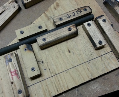
Work commenced on the battery tray support... Took my measurements per my reading on 2wings; Made sure it was level. Confirmed that the measurements were right. Wrote it down then made the jig.
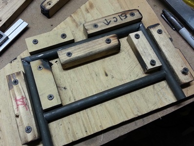
Took the 14inch chop saw out to cut the 45's on the tubes. Snapped them into the jig... they're ready to be tacked then welded.
Alluding to the second sentence I wrote tonight... an overwhelming feeling creeps in whenever I (you) start something new. Been there before. I'm in it now... and I'm sure I'll be back here again. I get through it with the help of friends; here, at the airport, on the forum... and from Tony B's books.
December 20, 2014
All juiced...
except the actual battery...
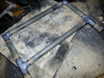
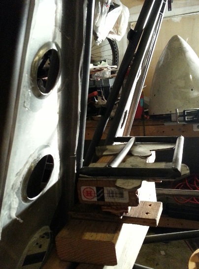
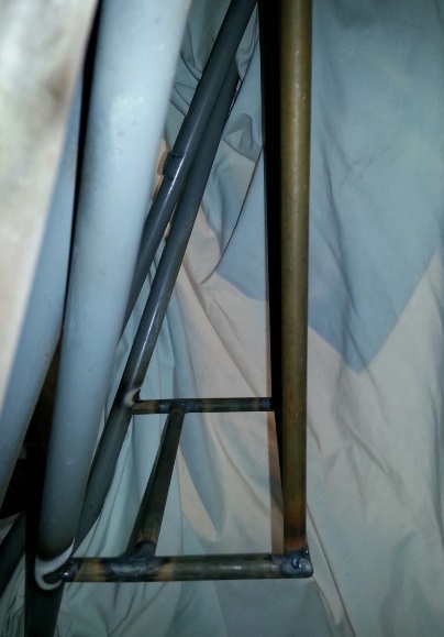
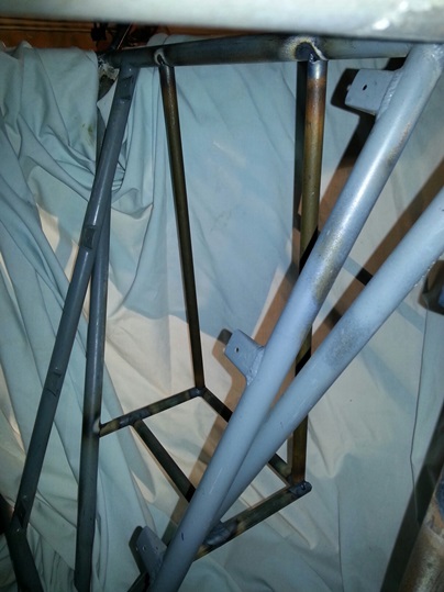
I was on auto-pilot today. Grinding through... tacking and welding up of the battery tray frame. Then... leveling, measuring and tacking it onto the fuselage. Folowed this up with measuring, grinding/notching of both hanging, support tubes that are a part of the battery tray support system.
Welded this all up (well, kinda close to having it all welded up). Still needs to have the .o40 4130 metal shelf tray cut out and welded to the frame. I plan on drilling a few lightening holes in it to shave a few onces off of it.
From my reading of Tony B's red book, "Firewall Forward"... it looks like the starter solenoid needs to be mounted close to the battery. I think I'll weld on a few tabs for this and securing the battery cables so that they're not pulling at the connections.
Next session, I'll check all the welds and then ???
December 21, 2014
Working on the project...
Not really.
Stopped by Woodstream Court on the way home from dropping my mother off after meeting wtih family (a Christmas cookie swap). I knew I had, and I wanted to look for, the list of brackets that need to be made and welded to the fuselage before sand blasting.
While looking for it I went through quite a few pages of written notes. side note: I need to get them in some sort of order... placed in folders for easy finding. I have stuff that's useful that I didn't remember I even had. One of them... stuff for the radial engine that I need to be looking at now.
anyways... I wanted to post this list so that I won't lose it again. Click here for that list.
add... plate for attaching tab to rudder
December 24, 2014
Making a list and...
Checkin' it twice...
Stopped by Woodstream Court... Christmas Eve day. Not a lot of time to do anything... at all on the biplane. BUT, I looked at it (been doing a lot of that lately) to see what I want to do next on it (been doing a lot of that lately).
I have a list... I've HAD a list of all these items. Guess, I'm just checkin' it twice... or maybe three... four... five times ???
December 26, 2014
Making another list...
that I really didn't want to check twice...
As usual... had the day after Christmas off. NJDMV was open so I stopped by to re-new my month-expired drivers license.
With business taken care of it was time to have some fun... over to Woodstream Ct. to work on the biplane project.
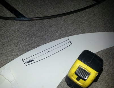
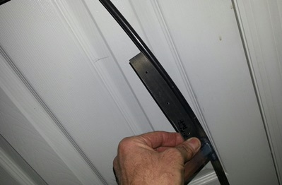
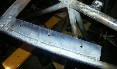
Just a lot of little things left to make and attach to the fuselage. Pick one... any one... and I'll make it. Pulled the mounting bracket for the rudder trim tab out of the air... Check the plans; it's 3/4inch x 6inches. Made out of .o32 4130. Took a piece of display board over to the rudder... drew the trailing edge to fit the curve of the rudder. Marked 3/4inch out from both ends and drew a straight line to connect the two. Measure and marked for three holes.
Found a piece of 4130 and traced the pattern. Marked the hole locations. Cut the metal. Ground down to size. Drilled the location holes. Filed and sanded the cut edges. Ready for welding on the rudder.
The next idea that landed on my lap was the trim/servo tab schtuff. I could have sworn that I took inventory to make sure I had everything I needed but... not so. Looked over the plans again to make a list of all the tubes that I needed to complete the trim/servo schtuff. As I looked them over I saw a notation that Hal said to change something from 3/8inch to 1/2inch. The note said it was mentioned in Hal's builder's notes. For the life of me I couldn't find those notes... and I know I have two sets of them. (I actually took 1 hour off the time I spent on the project today because I looked for these notes). I finally gave up the search and tried figuring it out. By looking at the various parts that need to be reamed and the parts that fit inside of said reamed part... I figured it out.
On the plans (page 14 of the Standard Skybolt plans) it says to ream the 5/8inch tube to 3/8inch. That's ain't so. There's a end tube, that is welded onto the 3/8inch tube that needs to spin inside of that 5/8inch tube. And... that tube is 1/2inch. So, ream it to 1/2 not 3/8inch. I need to order a few pieces of tube to make this trim/servo tab AND thinking it all the way through... I figured out I needed to purchase a 1/2inch reamer. I'll order these up this weekend. Maybe, hopefully I'll have these for next weekend.
oh... yeah... here's a few photos from the making of the mounting bracket for the rudder trim tab. Still needs to be welded on...
Note: All this stuff for the trim/servo tab needs to be on the stabilizer's page. Click here...
December 30, 2014
Stop looking at it !!!
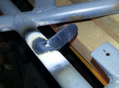
I had the rudder trim bracket in my hand... I knew what I was going to do with it but I just kept looking at it.
well, actually... It was more than a stare. I was visualizing how I was going to jig it so that the bracket would be flush on the left side (per the plans). I can understand thinking things through, but come on, Jer... do more than just stand and stare. and yea... It happens a lot.
Twas a simple thing to do... jigging the bracket for the rudder trim tab. Jigged it. Welded it up... all done.
(NEXT...)
Had looked at the plans the last time I was at Woodstream... and had an idea of what I wanted to do... but had another looksee to see what I wanted to knock out next. After looking at the plans again I planned on doing what I had originally planned; making the tab brackets for the brakes and the front rudder pedal spring bracket.
There's nothing on the plans to tell you how to make them; any real dimension other than the .o70 thickness of the 4130 material. Had some of that on hand so I crafted what looked to be what they were showing on the plans. now... They don't explain that these get mounted right under the rudder pedals, but that's where I'm thinking they go. It would only make sense since the connection on the brake part of the pedal is centered on the foot pad. If I was just going off the plans it looks like they're mounted on the outside of the fuselage... yeah, didn't make any sense to me either.
and... While I was at it I decided to make the square brackets that the rudder pedal springs hook onto. These are square looking things and the plans don't tell you how to make these either. Other than showing a square patch of something that's welded to the front, lower corner of the fuselage... there's nothing. Not even a material thickness. Figured that the .o70 thickness worked for the brake system it sure as hell will work for holding this spring (and the .o50 thickness didn't quite measure up to being thick enough) so I drew up a few 1 1/2inch squares on a piece of paper. Sprayed glued these to a piece of 4130. Drilled the holes. Rough cut them out. Ground to size... then filed the edges.
Time ran out for the day so I'll have to sand the edges of these next time... along with welding them onto the fuselage.


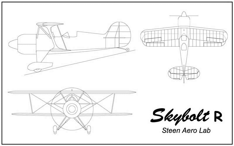
 So... I've got to choose one to start with and I figured I'd make it the battery tray. The Standard Skybolt's plans clearly show where to place the battery and what to make it out of (or at least what tubes to use to make the support frame for the battery box). Gives you two options depending on what size engine you're going to use. The Radial Skybolt's plans... not so much. I search the plans and only when I compare the two do I finally see what appears to be the battery placement and what tubes are to be used. Their ain't a whole lot more than a side view of the shelf. Not complaining... but that's all there is. Not much more on the Standard's.
 There's going to be a series of questions based on the answers I receive from a previous question. It'll take forever to get there by asking questions on the forum. I need to get over to see Whitey at the airport. But for now... I'll be taking a look at the "red" book in the series that Tony B. wrote. It's a compilation of the Firewall Forward articles that he wrote for EAA's "Sport Aviation" magazine. I haven't given it much attention yet, but I'm about ready to dive into it.