Mantua, New Jersey
Original Site:
September 2004
E-mail: usav8or@yahoo.com
Three-piece upper wing... stronger than Babe the OX.
June 27 - July 3, 2022 Scratch build... if you have the time.
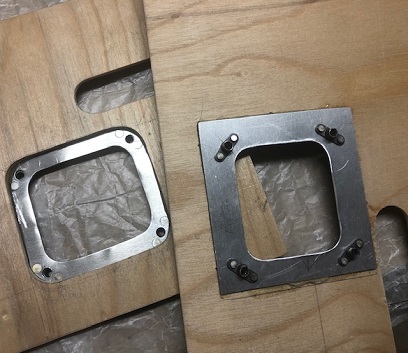
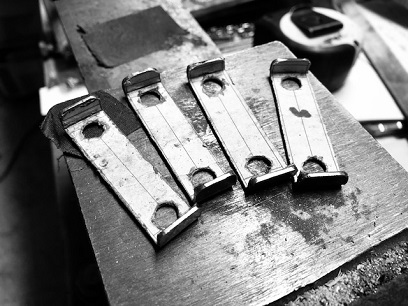
Wow! It took me close to 10 hour to make four custom washers... something the kit builder would have simply pulled out of a box and bolted onto their project. WoW!
I could probably shave about two hours off of that time... the damn printer! Or should I say, the damn computer. I've been connecting the computer to the printer VIA Wifi. NOW, it decides not to work. The computer, for some reason, isn't finding the printer. So... I went out and bought a printer cord. NOW... it has no reason NOT to find the printer since it's connected directly to it.
But before I bought the cord, I tried doing it by hand (and I knew before hand that I wouldn't be happy with the outcome, and I wasn't). NO JOY!
As mentioned in my last post, I'm making these instead of doing the safety wiring of the bolts. In hind sight... it would have been quicker and easier to safety wire them. Anywho... ten hours later and I have them ready to be used on the uwcs.
HAPPY Independence Day!!!
Custom washers - ready for paint (almost).
Painted and ready for duty, Sir!
July 4 - July 16, 2022 Paint... if you have the time.
Not sure about painting...
I've spent an excessive amount of time painting and touching up the spar brackets and I'm STILL not happy with the outcome. One: The glossy paint never gets that smooth finish. I'm always having to sand it. And Two: If I man-handle the piece it seems to chip. Now... I'm not talking about BANGING away on it. For instance, I'm sliding the outer box ribs into place and part of the paint chips off. Like W!T!H!???
I'll finish up figuring out the plywood and the bolt, nuts, etc. then I just might send them out to be painted.
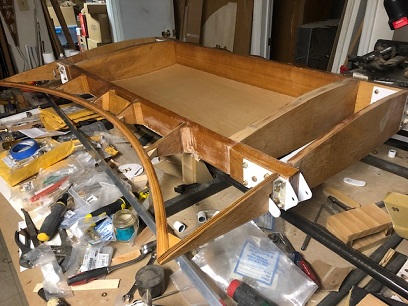
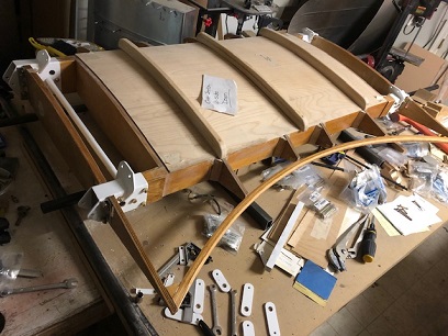
Other than me paiting and then re-touching up these spars brackets umpteenth-times I did accomplish a few other things. I dove back into the plans to make sure I'm finishing up the Upper Wing Center Section right. Had a slight issue with one of the holes on both of the outer box ribs fitting up with the rear L-bracket on both sides. Confirmed that each was in the correct place (after filling the hole with T-88) and re-drilled. (still scratching my head on that one) With the pieces all in place I could measure and cut and notch both outer panels for the bottom of the Upper Wing Center Section. (The plans call for one piece, but I decided to do them in three pieces. There is plenty of surface area to glue plywood in three pieces. And making them in three pieces allowed for easier notching for the spar brackets.)
One of the many times I touched up the paint.
Ready for the outer ply.
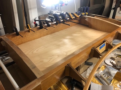
Both outer plys notched and fitted.
July 18 - August 13, 2022 Doesn't matter what I do....
it's all slow.
Moving on from the painting... for the time being. Trying to knock out, as much as you can knock out on a piece of the project, the UWCS to the point where I can place it aside with everything but the top portion to be enclosed after jigging the UWCS wing tank in place.
It's been going a lot slower than faster. Re-re-measuring the bolt lengths (apparently I didn't take into account the thickness of something, or I made a change of plans between ordering and then doing the trial fit.) In any event, I'm going to need to buy a few more pieces of AN hardware for the fitting. Not a problem... other than it being a problem because it's extending the days spent on this. NOW, I'm second guessing myself and I am hesitant to place this second order.
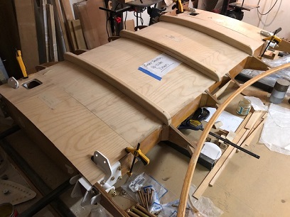
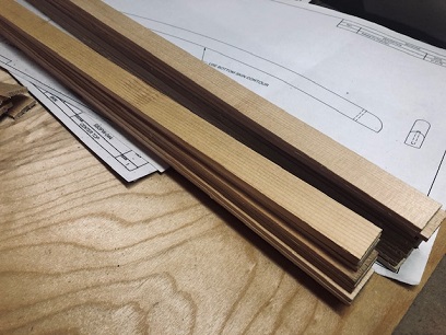
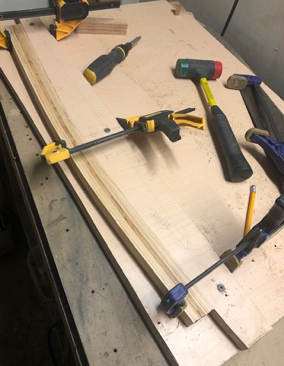
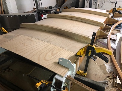
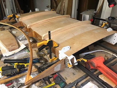
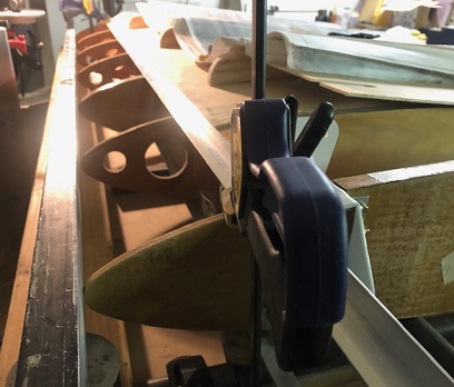
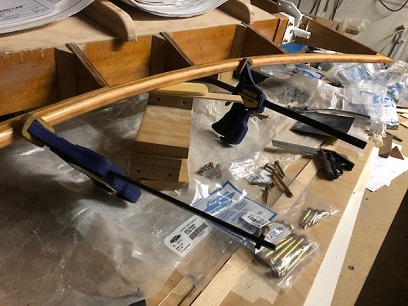
With my head half-wrapped around that thought, I started working on the bows (tank supports) for the UWCS. These consist of layered up 1/8inch Sitka Spruce. The pieces are 7/8inches wide and when stacked and glue are about 1 1/2inch high. I decided to make a jig using the curve of the UWCS belly as a template. I made the jig in such a way that I could lay them on their side and clamp them in place over night.
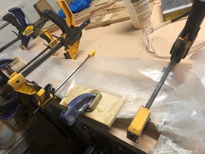
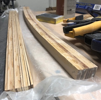
Made the jig... cut the Sitka to length... then glued and clamped. Took a look the next day and it was near perfect. All I needed to do was add a sliver of a filler piece on the front of it and then sand it to fit. Adjusted the jig for the second one... and took two days to knock out the 2nd and 3rd bows. Each of these were closer than the first, but still needed some wood filler adjustments. Drilled the holes and tried them on for size.
Just a note:
Don't allow the current lack of speed alter your thinking and allow the thought that "Good enough is Good enough". Don't allow it! Keep on keeping what you are doing. Slow... maybe at times, but keeping your standard of Excellence...
I'm near finish with making the tank support bows. But there's still plenty to do on the UWCS before setting it aside to work on the cowling ring/nose bowl...
Photo essay... start to finish of the tank support bows:
September 21 - October 29, 2022 If I could only get....
these brackets painted.
Moving a little forward on this project I've been working on.
Let's see... the painting of the brackets is an ongoing story. Just yesterday (9/9/2022) I found out Joe Flood doesn't paint any more (pretty much retired?). So... I'm cleaning up the little nicks that I have on the brackets I painted and will be giving them one final, nice coat of paint. I'll then put these puppies on the UWCS and then glue the remaining wood in place.
While messing with the brackets... I finished up with the cutting, shaping, and drilling of the three bows for the tank supports (these attached under the upper wing center section, just under the upper wing fuel tank).
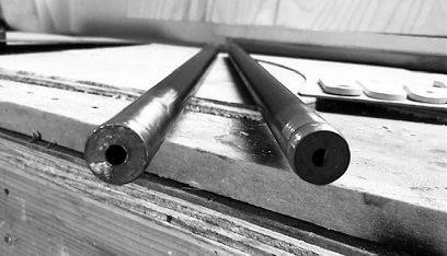
Another small project that had been sitting out there... welding the threaded inserts onto the two compression tubes for the UWCS... put a check next to that "to do". All finished and ready for paint.
Now throw in a few hours of hardware inventory, and reading up on WTF you need to do when working with composites (making of the cowl ring mold)... and you flesh out these past few weeks of work on Big Ass Bird.
August 14 - September 10, 2022 A visit to Mexico...
and the project patiently waited for me.
"Oh, Mexico. It sounds so simple, I just got to go. The suns so hot, I forgot to go home. I guess I'll have to go now." (Jimmy Buffet - Mexico)...
I've been in Mexico with Fernanda for the past month. Worked remote the first two weeks and then vacation for the next two weeks. Had a BLAST! Saw quite a few museums and parks in Mexico City, ate out at few of Fernada's favorite restaurants, visited with a few of her friends... then headed out; Tepoztlan, San Miguel de Allende, Santuario de Atotonilco, Mineral de Pozos, Coatepec to visit our macadamia plantation, Xico. It was a beautiful visit!
I also spent a lot of time when in Mexico thinking of how I wanted the cowl ring/air intake to look so that I could finalize the plans for making it. Plans... meaning how I would make the plug for the mold to make the final cowl ring. None of that time is being recorded in my log.
I think I have the look I want now... it's all a work in process, so it may change slightly between now and the finished piece.
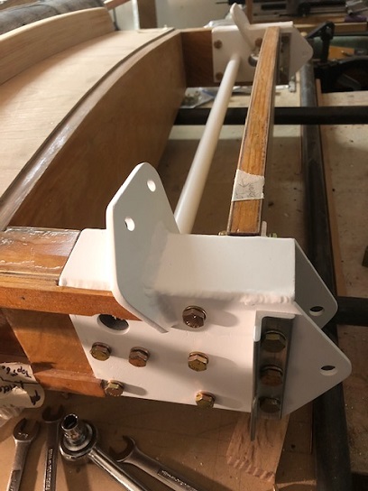
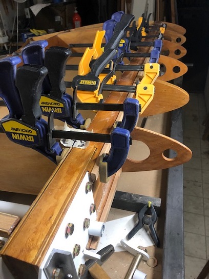
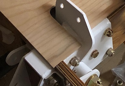
Moving forward on the UWCS. I pretty much have the brackets and tubes painted to my liking. Fitting up the brackets to the spars I discovered that I needed to sand down the thickness of the spars to allow the brackets to fit without scraping off all the paint on the inside of the brackets, then a re-seal of the spars with some Clear Coat. And since then I've been wrenching on the nuts and bolts on the brackets.
It might now look much different than before, but the hardware is now wrenched on (I need to readjust a few of the bolt lengths) and gettng ready for me to glue on the outer two piece of the lower side and glue/screw on the three wood tank supports.
October 30 - November 5, 2022 A lot of wrenching...
and staying with it.
The Upper Wing Center Section... MAN, there's a lot to do on this. This MIGHT be the bigest project I've worked on. There's the fuselage, with all it's bits and pieces. But they were more or less done as individual smaller projects. The Upper Wing Center Section... just seems like it's going on forever. Again, I enjoy the process, but there's a lot of bolting on and un-bolting without getting much further along than making adjustments.
It's this bolting on and off that I need to deal with. I generally
want to push aside tasks like this for a later time. If you don't watch it, these will quickly
catch up with you and you've got this huge number of "push aside
tasks". I digress... So, I'm taking care of these "push asides"
now as they are happending. Un-bolt many bolts. Do something
to un-bolted part. Bolt back on. Un-bolt many bolts. Do something
to un-bolted part. Bolt back on. Un-bolt many bolts. Do something
to un-bolted part. Bolt back on. Un-bolt many bolts. Do something
to un-bolted part. Bolt back on. And I'm just not moving forward
with much new being built and attached.
(ad infinitum)
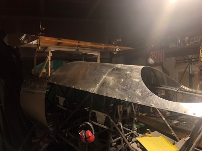
Okay... I got all that un-bolting/bolting back on all finished for at least now. All that un-bolting/bolting back on wasn't for not... Some of that un-bolting/bolting back on allowed me to begin the process of aligning, sizing and bolting on the two outer nose ribs to the Upper Wing Center Section. Unbolting the two L-brackets allowed me to drill the holes for the four AN3 bolts that will attach the nose ribs to those two L-brackets.
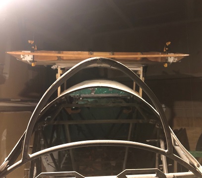
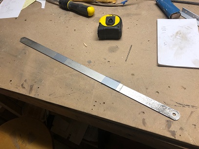
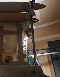
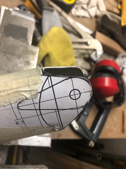
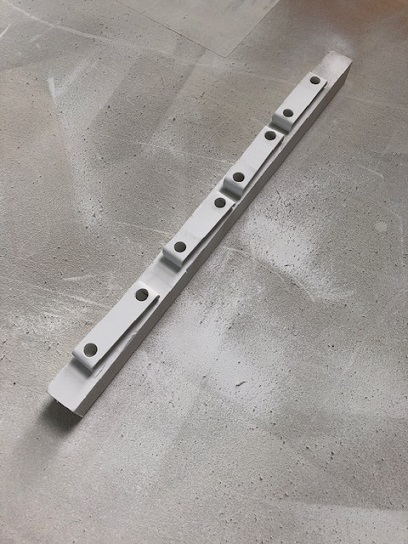
I found a few straight edges, aka long pieces of metal that
allows me to align the two outer nose ribs with the five other
nose ribs. Two lengths of L-shaped extruded aluminum pieces
are being used for the upper and lower alignment tools. A 10ft
length of rectangular box tube works well for aligning the tip
of the ribs. The top and bottoms line up... the tips of the
two outer nose ribs are about 3/32nd too long (which I knew
because of the thickness of the spar brackets.) I'll let everything sit
over night before sanding down the back of both nose ribs. If all looks good tomorrow I'll sand them down.
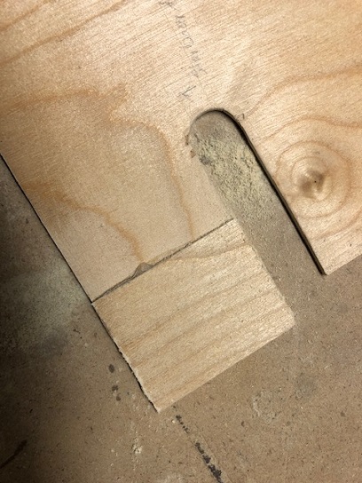
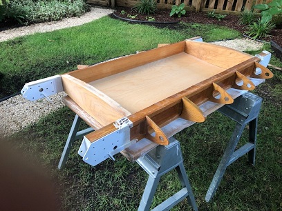
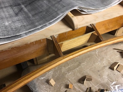
Another project I tackled over the past few days was aligning and permanently glueing on the bow/hand hold. Another one of those projects that could only be done after a countless number of un-bolting and bolting back on's. Once glued into place I started working on boxing in the actual hand hold area of the bow. The most difficult part of boxing it in was finding a piece of aircraft grade plywood that was about 1/4inch thick. Most of the stuff I have saved were too short. Finally found the piece I needed and cut it to length, and height, glued on the triangular gussets, sealed, and then glued into place.
All this un-bolting and bolting back on is giving me a taste of that "90 percent done, 90 percent still to go."
Getting ready to lock in the two outer nose ribs.
Bow glued in.
Boxing out hand hold.
Some of the unbolt/bolt back on bolts.
November 7 - 20, 2022 Ready to cue up
the next big project.
Still tackling the upper wing center section (although, I've been spending hours reading up on fiberglass and carbon fiber so that I can make the cowl ring/air intake).
I think I'm having a harder time wrapping my head around what size bolts (lengths) to use than any other thing on the center section. I'm either forgetting to add in there the thickness of a washer or two... or something. Not quite sure. By the time I'm finished buying the hardware for the spar brackets I'll have enough hardware to complete the entire biplane! Essssssh!!!
Another head scratcher for me was how to attach the upper and lower skins to the spars. Let me re-phrase that. I was a little confused when I saw instructions on the original drawings drawn by Curtis Pitts to attached the upper skin of the Upper Wing Center Section to the spar brackets with sheet metal screws and glue. A RED FLAG went up... should I be drilling holes into the spar brackets and screwing in sheet metal screws??? Wouldn't that cause all kinds of stress on the part?
Asked the question on the biplane forum... didn't receive an answer. Nobody wanted to speculate a yes or no... none of the other biplanes out there are like this. I can understand their hesitancy in answering. So onto Plan B... ask the guy, who use to own the most kickass Pitts rights. Sent him an email and got my answer. Details to follow...
So, between tending to all the little things on the Upper Wing Center Section, and cutting some wood for the plug for the cowl ring/air intake, I've started reading about fiberglass and carbon fiber making. More on that on the Cowling fiberglass/carbon fiber page...
Finally! The upper wing center section right-side up.
Cap strips clamped in place.
Said, cap strips...
November 20 - December 11, 2022 Shit...
a lot of the good kind.
A lot of little shit is getting done... but it's a lot of little shit that is closing the book on this part of the upper wing center section build.
Blah blah blah... right? A few important things to think about...
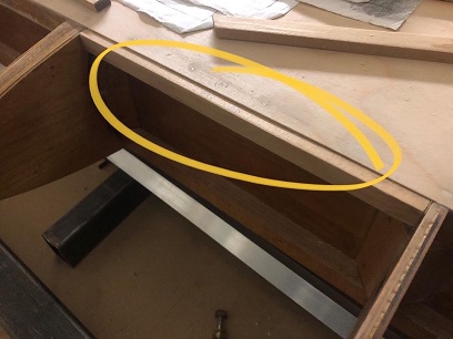
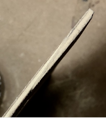
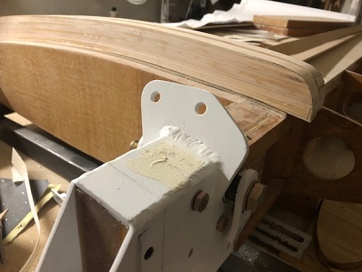
One: The trailing edg of the ply on the under-side of the upper wing center section needs to be addressed before cutting it per the plans. At least that is my opinion. As you can see in the photos below, the outer part of the plywood, that is over the spar bracket falls short of the outer most trailing rib sections. I didn't like how it looked... and probably how the fabric would look over that section once attached, so... I decided to scarf a section of plywood in each of those two areas. NOTE: you need to have either 10:1 or 12:1 scarf for the area you are working on. I sanded down the area by hand, and it wasn't that difficult to do. Not perfect, but DAMN! close! I'm happy with the way it looks now. So if you are aware of this before cutting your plywood for the under-side you'll save yourself a few hours of scarfing... or maybe you want to learn to scarf?
Ply too short.
Scarf
Scarf - still needs cleaning up.
Length... just right.
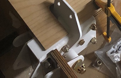
Two: You'll need to put an access hole in the forward area of the upper wing center section... access to the drag wire attachments AND for the drag wires. There AIN'T much room up front for the access hole/opeing for the drag wires.
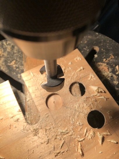
The cover for this area was an entire process of creating flange plates that the access cover could attach to; cut the correct size opening for the hole, figuring out the size and thickness of the flange plate, cutting the plate, drilling the holes, match-drilling the anchor nut plates for the machine screws that will hold on the cover. Yeah... about 20 hours worth of fun (it actually was fun) for all of the work I needed to make the holes, flanges, etc. All I need to do is make the cover plates for both of these and they'll be finished. Below are a few images of the process.
One and two above pretty much took up all my time over the past few weeks. Keeping busy... enjoying the ENTIRE process.
Drilling/cutting out access hole.
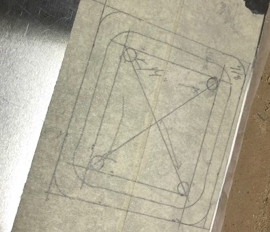
Flange plate drawing.
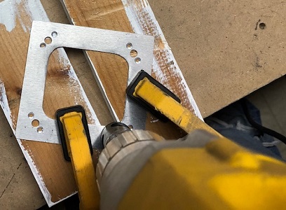
Drilling holes for anchor nut plates.
Flange plate glued onto plywood.
Beauty shot of under-side of center section
showing access holes and flange plates.
December 13 - 24, 2022 Shit !!!
3 sets of plans...
1 Big Ass Bird !!!
Back to that same stuff again about three plans for one biplane... Trying to make sense of the two different sets of plans for the Radial version. Curtiss came up with the original set and for some reason Steen (Maybe Curtiss?) changed the upper wing center section all kinds of ways.
The original plans by Curtiss, the upper wing center section (USCS) didn't have the compression tubes. The CAD version does. The original had the sway wires on the back spar, the new one has them on the front spar.
The Pitts 12 has them on the back, another Curtiss design, but I just saw the sway wires on the front of a well engineered design, the Skyote. After a lot more debating (in my mind) I'm moving forward with the CAD design.
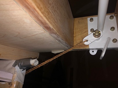
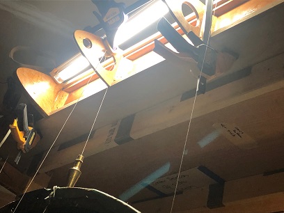
I lifted the UWCS 15inches above the upper longerons (kinda makin' look like a racer). The plans say it needs to be at 21 1/8inch. The sway wires, upon my "twine test" doesn't clear the inner box spar of the UWCS with it at the 15inch height. Thinking... lifting it up to the 21 1/8inch will do the trick of clearing the inner box spar. Need to make that jig now.
Hours spent debating something that shouldn't have to be debated. All this time and I'm still at the same point (other than arriving at a decision) that I was close to a week ago. Ahhh... the beauty of a scratch built, almost one of the first of its kind biplane.
Merry Christmas... Happy Holidays!
At fifteen inch height.
View at fifteen inches.
Twine test at fifteen inches. A bit of
rubbing going on.
December 25, 2022 - January 14, 2023 DON'T RUSH !!!
This stuff is important!
Figured it out... always do! But it's at these times I just want to get it over with... the figuring out that is. I feel that if I'm not cutting, drilling, welding, something physical, I'm wasting my time. BUT... figuring out things is a part of the build.
Lifted the Upper Wing Center Section into place at the correct height AND, using plum bobs, aligned it to the firewall. Click here for a few images showing my numbers for where the leading edge of the front spar needed to be height-wise and alignment-wise to the firewall. Page 1, 2, 3, 4. My numbers calculate that the front of the spar needs to be .825 from the rear of the tubing at Station Zero...
The past few weeks have been 1. Figuring how high to lift the UWCS. 2. Alignment of the front spar on the UWCS to the firewall. AND 3. Figuring out the lengths of the struts. oh yeah... AND 4. Figuring out how to squeeze the ends of the struts from one inch to 7/32nd inch.
1. Going back to what the CAD plans suggest for the height resolved the possible issue of the wires rubbing up against the inner box spars on the UWCS. And that is lifting the bottom edge of the front spar 21-1/8inches from the top of the longerons.
2. A lot of head scratching for figuring out the location of the leading edge of the front spar to the firewall tubing. As noted above... I've determined that the leading edge of the UWCS front spar should be .825inches from the trailing edge of the tubing at Station Zero. I calculated that by figuring out the distance between the lower and upper spars on the Standard Skybolt. And looking back on a thread on the biplane forum... saw that every one was in agreeance that since the bottom front spar was moved 8inches forward the top wing needs to be moved 8inches forward.
Okay... that was the easy part. Now to figure out the location of the Standard Skybolt's upper wing's forward wing spar's center so that I could determine the UWCS's forward spar's center section. AND once determining that I could figure out the distance between the tubing at Station Zero and the leading edge of the UWCS's front spar so that I could drop plum bobs and get this thing in position. Those drawings I mentioned earlier are easier to understand than if I were to scratch the numbers out here on paper. Click on previous links above to view my scratchings.
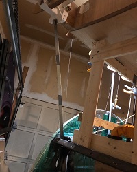
3. NOW the easy hard part. Made a simple sliding jig, similar to what I made to figure out the tubing length on the motor mount. Took two lengths of 1inch x .o32 4130 and drilled a 5/8inch hole at the end of one side on each. Bolted each piece, one to the UWCS bracket and one to the fuselage bracket, and then taped with duct tape to keep it from moving. And WA-LA! Perfect measurement!
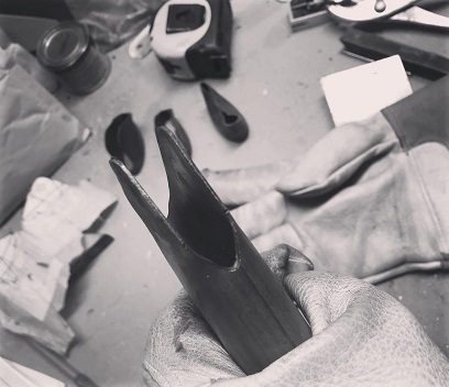
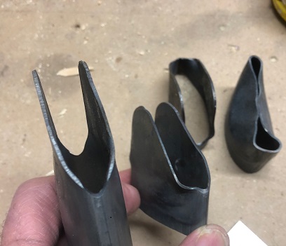
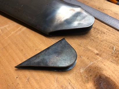
4. Now the hard part... figuring out how to squeeze the ends of the streamline tubing to match the plans. So, I'm taking one inch down to 7/32nd inches. A few test pieces and it was easy enough to take down to 1/2 inch. Squeezing that additional 9/32nd's a bit more of a challenge. I'm still working on it but think I've got it figure out.
Rough cut test piece.
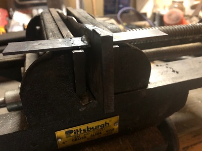
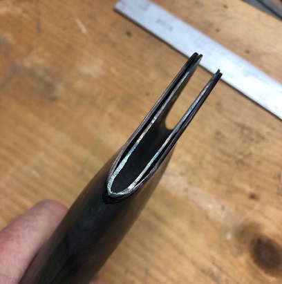
Jig used for 7/32nd spacing while squeezing strut ends.
Fourth test piece.
Above test piece, different photo angle.
One through four test pieces.
I'll need to leave a sharp notch in each sides of the opeing (on the same end) so that I can correctly center the tubing. Also set up a visual clue for making sure that I keep the tubing at a 90 degree angle to the bench top. This will cure both the off-centerness of the test piece and the slight angle to the ears of the strut's end.
January 14 - 28, 2023 Not RED Hot...
just hot.
These past few (many) days have been about strut ends, and squeezing said strut ends. And thinking you had the process down and then understanding said process needed more refining.
Okay... if you've read the past few BLOG posts you've read about my many test piece practices, both failure and SUCCESS. With all that learning I thought I was ready to make the real things. Well, I was in a sense...
I figured out that I needed a wider template jig to squeeze the strut ends... just like my original one (duh!). The thinner squeeze template jig I tried my first, "finished" strut on was .190. Turns out that this was difficult to keep vertical AND I discovered there is a divit on the stationary side of the vice so when you get close to having it fully squeezed the thinner squeeze jig falls into the divet and angles itself. NOT GOOOD.
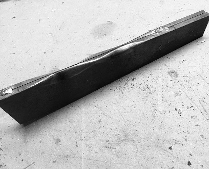
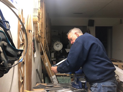
Not knowing this I, full of piss and vinegar because of the latest success I've had... heated the strut end RED hot and squeezed confidently... slowly but confidently. Opened the jaws of the vice and started extracting the strut... daaaaaaaamn. The end was deformed, angled and part of the one side was weirdly deformed. There was an accute angle in the one leg of the fitting's end. Whiskey Tango Foxtrot!!! What the heck!?!?!?
DAMN! Luckily I cut it long enough to be used for one of the back struts... Okay, what did I learn from this first real attempt at squeezing these struts? I learned that I better start doing a better job because I don't want to be buying more streamline tubing at $35.00 per foot... THAT's what I learned.
Okay okay... another test piece with a scrap piece of streamline tubing I had... decided that I needed to used that wider jig... one that was closer to 1/2inch wide and be happy with the wider opening in the strut end (maybe weld on a couple pieces of 4130 to fill that gap, or use a few washers?... I wasn't quite sure at the time, BUT I WASN'T GOING TO F-up ANY MORE TUBING!!!)
Cutting the strut end.
Cut, ground down, filed, and sanded another end to squeeze. Heated that puppy up to a red hot, placed it in the vice and squeezed ever so carefully. Crossed my fingers and slowly released the grip the vice had on it... slowly pulled it out of the vice... first side looked good... turned it around and WA-LA the second side looked good too! Now all I had to do was repeat this seven more times and I'll be in the clear.
Back to the workbench to repeat the align pattern, rough cut, grind, file, and sand process for the second end on the first strut. Ready go! I'm getting pretty good at align pattern, rough cut, grind, file and sand... and I hoped I was getting better at the heat and squeeze too.
The second end of the first strut was ready for the trial by fire... literally. Went out to the garage workshop. Crossed my fingers. Lit the tourch. Heated the end... and for some reason unbeknownst to me as to why it happened... the second end of the first strut was a success as well. Thought bubble: Hey, I'm getting pretty good at this.
Somewhere along the line of me thinking this entire process through... the many days and nights of trying to understand why I failed after succeeding all those times before the failure... I think I came up with the answer I was looking for. I was heating the tube end up red hot. Getting the metal that HOT allowed it to be TOO malleable. With the tube end that easy to bend... any flaw in my technique was allowed to easily happen and magnified. Sort of like flying a Pitts Special compared to flying a T-craft. They're both airplanes, but the Pitts reacts much quicker than the T. Answer to my learning: heat the end up good and hot but not TOO hot! I push that redness around both sides of the end for awhile... to allow the heat to rise up the tube. I then allow it to begin to cool... not red at all when I insert it into the jaws of the vice. There's still plenty of time to squeeze it and get a good squeeze. Don't rush it.
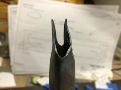
After completing the two front struts; completing them to the 1/2inch squeeze, I decided that I wasn't going to be happy with 1/2" gap in the strut end so I figured out a way to keep the .250 vertical in the vice. My initial thought was that I need feet on the jig to keep it upright. How was I going to accomplish that? They'd get in the way of the jaws on the vice, no? Maybe extend arms off of the jig so that I could make feet that would slide on the bench top? Thinking... there had to be an easier way than that. ANSWER: BINGO! I welded on wings to the sides so that it wouldn't lean over. The wings slide over the tops of the jaws and allowed the vice to close and still keep the jig vertical.
So here's the plan moving forward: Heat the streamline tubing (not too hot) and squeeze to 1/2". Next, cold squeeze the tube end on the 1/4inch jig with wings to get it closer to the 7/32inch width the plans call out for. And THEN (I haven't tried this yet) heat the end and squeeze it again over the 1/4inch jig. This should get it near perfect (within 1/32nd). Still not 7/32nd but DAMN close.
The take away... hot, but not RED HOT!
Red Hot before squeeze. That's a no no.
Wings on the .250 jig.
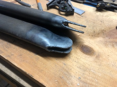
Hot squeeze on the 1/2inch on right. And first 1/4inch squeeze (cold) on the left.
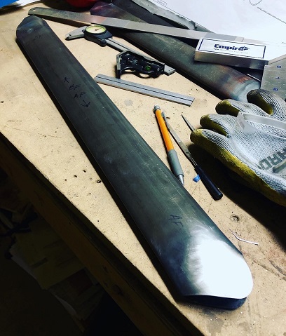
Half inch squeeze on both ends of first strut.
January 28 - February 5, 2023 The End is near!
Hell... I'm working on the ends.
The beauty of the familiar... Already over that hesitation to start. Past that learning curve.
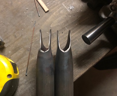
A few things left on the second end of the second strut... and then I made the final squeeze! BUT, they still don't look right...
The streamlined strut still looks like a tube. There's a hole going straight through it. Nothing on the plans tell you that you need to seal the ends or how to do it. I had my own ideas but threw the question out to the biplane form and received an answer from Jim, saying that the struts is similiar to the one that is on the Tailwind. I just happen to have a set of Tailwind prints so took a look.
The end is similar in that they are closed off, but in different ways. I have a set of Pitts 12 plans which I thought would have a similar end but ended up not even looking at them. Instead, I moved forward with my plan.
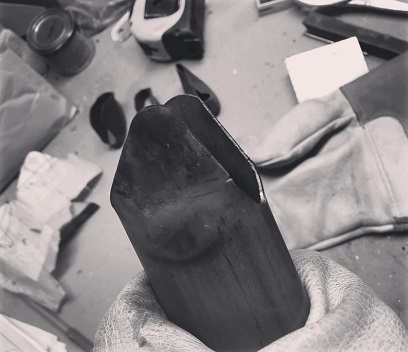
I took a sheet of .o32 4130 metal I had in my 4130 metal stash. Cut a rectangle to the size I needed. Took it and the .190 thick metal "jig" (I made for squeezing the strut ends) out to the garage workshop. Heated the center line where I would make the bend and started to heat and bend over the soon to be insert. Got it to the point where I had to take it off of the jig ('cause I didn't have any more room to bend it without hitting the side of the vice) flipped it over and continued to squeeze the piece of metal with the .190 between the pinched sides until it was fully closed on it. Let it set for a minute to cool then opened up the jaws of the vice. and WAA-Freakin-LA! I had an insert that has a .190 opening. It worked better than I wanted. I thought that there would be some spring back. Not. A. Chance... apparently.
Once cooled I inserted into the end of one of the struts. It was an easy slide into position. Had to open it up a bit so I re-heated it and pushed it over the .250 jig I made for squeezing and then closed the jaws on it. Let it cool. Slipped (rather pushed) it into the same strut end. Nice. Tight! Fit.
Proceeded making the other three in the same manner.
With a little help with a few small clamps I welded (LOVE welding THIN tubing) all four ends... Pushing that golden puddle.
Still need to drill the ends with 5/16th inch holes and then weld on the tear drop reinforcing straps. Started to drill the 5/16th inch holes in those... a total of 16 to drill.


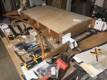
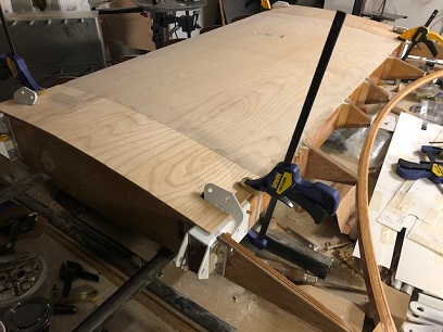
 Boxing out hand hold.